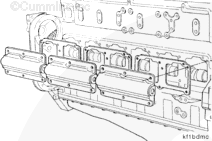
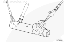
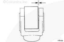
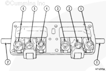
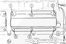
Remove the cam follower housing assemblies as follows:
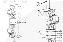
Remove the six capscrews and studs from each cam follower housing.
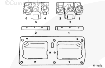
NOTE: Record the position of the studs prior to removal.
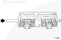
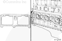
Remove the cam follower housings and gaskets.
NOTE: To prevent increased wear, mark the cam follower housing assemblies as they are removed so they can be installed into their original location on the block.
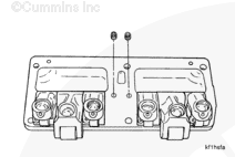
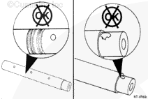
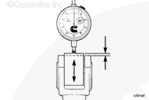
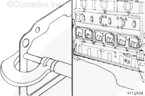
Remove the shafts and the cam follower levers from the housings.
NOTE: To prevent increased wear, mark the cam follower shafts and the levers as they are removed so they can be installed into their original positions in the housing.
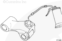
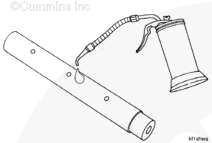
When using solvents, acids, or alkaline materials for cleaning, follow the manufacturer’s recommendations for use. Wear goggles and protective clothing to reduce the possibility of personal injury.
WARNING
Wear appropriate eye and face protection when using compressed air. Flying debris and dirt can cause personal injury.
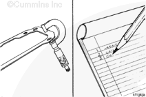
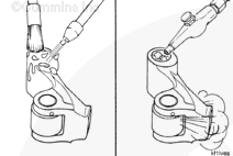
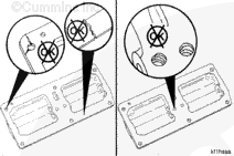
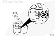
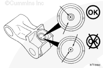
Inspect the sockets for excessive wear or other damage.
A good even seating pattern
must
be seen when inspecting the cam follower socket.
When parallel grooves and scratches are observed or the contact area extends into the oil hole chamfer of the socket, the worn socket
must
be replaced.
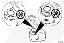
NOTE: If excessive wear or damage is found in the sockets, inspect the push rods. Do not use push rods with worn balls in cam followers with new sockets. Refer to Procedure 004-014 in Section 4.
Hello, I'm Jack, a diesel engine fan and a blogger. I write about how to fix and improve diesel engines, from cars to trucks to generators. I also review the newest models and innovations in the diesel market. If you are interested in learning more about diesel engines, check out my blog and leave your feedback.
View all posts by Jack


 CAUTION
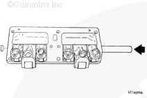
 WARNING


;)
;)
;)
;)
;)
;)
;)
;)
;)
;)
;)
;)
;)
;)
;)
;)
;)
;)
;)
;)
;)
;)
;)
;)
;)
;)
;)
;)
;)
;)
;)
;)
;)
;)
;)
;)
;)
;)
;)
;)
;)
;)
;)
;)
;)
;)
;)
;)