Do not remove the pressure cap from a hot engine. Wait until the coolant temperature is below 50°C [120°F] before removing the pressure cap. Heated coolant spray or steam can cause personal injury.
WARNING
Coolant is toxic. Keep away from children and pets. If not reused, dispose of in accordance with local environmental regulations.
WARNING
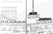
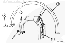
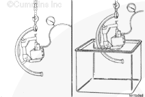
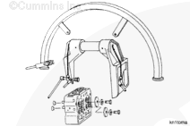
This component or assembly weighs greater than 23 kg [50 lb]. To prevent serious personal injury, be sure to have assistance or use appropriate lifting equipment to lift this component or assembly.
When using solvents, acids, or alkaline materials for cleaning, follow the manufacturer’s recommendations for use. Wear goggles and protective clothing to reduce the possibility of personal injury.
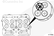
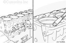
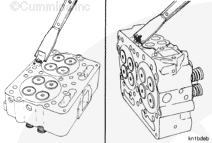
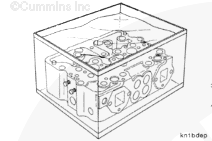
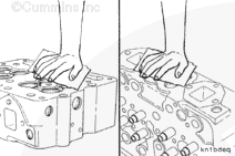
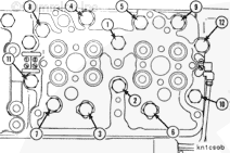
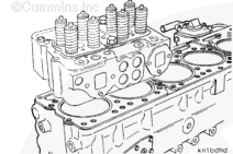
Use a razor blade scraper and solvent to remove any remaining material from the cylinder block surface.
When using solvents, acids, or alkaline materials for cleaning, follow the manufacturer’s recommendations for use. Wear goggles and protective clothing to reduce the possibility of personal injury.
WARNING
Wear appropriate eye and face protection when using compressed air. Flying debris and dirt can cause personal injury.
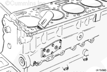
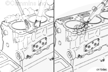
Clean with solvent and dry with compressed air.
Remove the cloths after the cylinder block is cleaned.
When using solvents, acids, or alkaline materials for cleaning, follow the manufacturer’s recommendations for use. Wear goggles and protective clothing to reduce the possibility of personal injury.
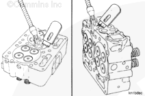
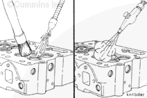
Use a razor blade scraper and solvent to remove any remaining material from the cylinder head gasket surface and the exhaust manifold gasket surface.
When using solvents, acids, or alkaline materials for cleaning, follow the manufacturer’s recommendations for use. Wear goggles and protective clothing to reduce the possibility of personal injury.
WARNING
Wear appropriate eye and face protection when using compressed air. Flying debris and dirt can cause personal injury.
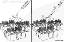
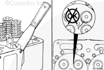
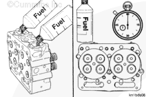
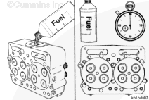
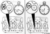
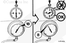
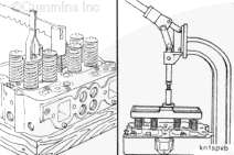
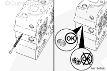
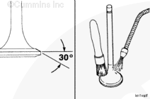
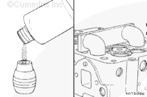
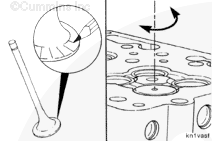
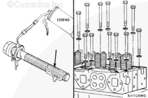
If a drop of fuel drips or runs down the face of the head within 30 seconds, the intake valves and the seats must be resurfaced. Refer to the N14 Shop Manual, Bulletin 3810487.
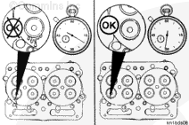
If a drop of fuel has not run down the face of the head in 30 seconds, the intake side is okay.
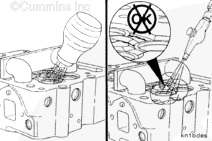
If the elapsed time is less than 10 seconds, perform the following checks:
Repeat the test to make sure the equipment is operating correctly.
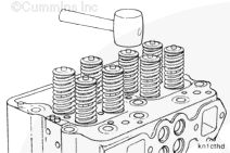
Use a mallet to lightly hit the valve stem to make sure the valve is seated. Repeat the test.
Apply a thin layer of grease on the outside diameters of the insert and the valve head. Repeat the test. The grease pattern will show the point of leakage.
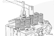
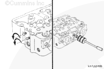
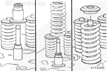
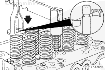
Use a valve spring compressor, Part Number ST-448, or equivalent, to compress the valve springs.
NOTE: Install a wooden block between the valves and the head holding fixture to support the valves.
NOTE: Valve spring stand, Part Number ST-1022, and the compressor plate, Part Number ST-1026, can be used to compress all eight springs at the same time.
NOTE: Mark the location of the valves with an engraving tool as they are removed. The intake and exhaust valves are manufactured from different materials. The exhaust valves can be installed in the intake valve location. Do not install the intake valves in the exhaust location.
Repeat the procedure to remove the remaining valve collets, retainers, springs, stem seals, and valves.
When using solvents, acids, or alkaline materials for cleaning, follow the manufacturer’s recommendations for use. Wear goggles and protective clothing to reduce the possibility of personal injury.
WARNING
Wear appropriate eye and face protection when using compressed air. Flying debris and dirt can cause personal injury.
Remove the cylinder head and components from the cleaning tank.
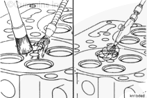
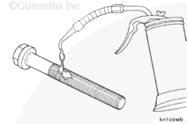
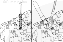
Use a fuel passage cleaning brush, Part Number ST-876, to clean the fuel and oil passages with solvent.
Dry with compressed air.
Inspect the fuel and oil passages to make sure they are clean.
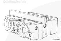
Clean the combustion deck exhaust and the intake manifold gasket surfaces with a Scotch-Brite®, Part Number 3823258 or equivalent, and diesel fuel or solvent.
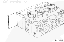
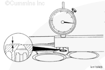
Use a straight edge and a 0.003-inch feeler gauge to measure the flatness of the cylinder head gasket surface.
Flatness Per 25.4 mm [1.00 in] of Length
mm
in
0.020
MAX
0.0008
Flatness Per Total Overall Length
mm
in
0.08
MAX
0.003
NOTE: If the cylinder head is worn more than the maximum specified above, the cylinder head must be resurfaced. Reference the Alternative Repair Manual, Bulletin 3379035.
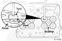
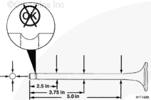
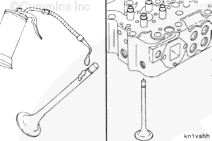
Use the valve head checking tool to measure the head thickness of the valves.
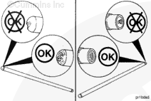
NOTE: Install the valve on the tool with the valve head contacting the tool as illustrated. If the valve head is even with or extends beyond the end of the tool, the valve can be reground. If the valve head is below the end of the tool, the valve is not thick enough for regrinding.
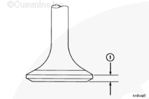
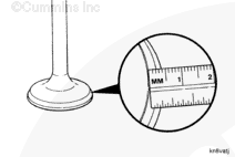
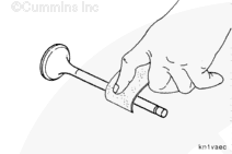
If a valve head checking tool is not available after regrinding the valve seat surface, place the valve on a flat surface and measure the head thickness (1) at the outside diameter.
Valve Head Thickness (Outside Diameter)
mm
in
2.90
MIN
0.114
NOTE: If the valve head is thinner than the minimum specified, the valve must be replaced.
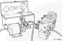
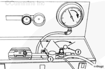
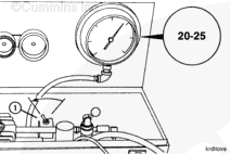
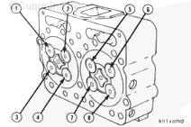
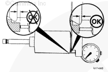
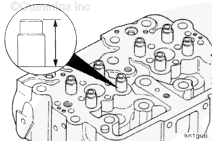
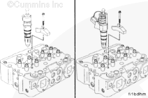
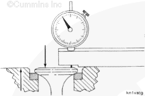
Perform the following steps to check the injector seating quality in the injector sleeve and to measure injector protrusion past the combustion face.
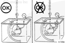
NOTE: Support the cylinder head to prevent damage to the injector tip which protrudes from the combustion face.
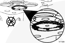
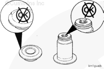
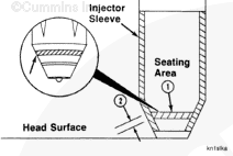
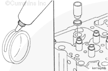
Apply a very light film of blueing compound to the outside diameter of the injector at the injector seat area. Blueing compound can effectively be applied by hand or with a brush.
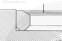
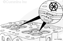
The blueing pattern in the injector seating area (1) must be visible 360 degrees around the seating area.
The injector bore seating width (2) must be a minimum of 1.52 mm [0.060 in].
NOTE: If the injector protrusion is more than the maximum specified or if the injector sleeve blueing pattern does not meet the specifications given, the injector sleeve(s) must be replaced.
NOTE: If the valve guide inside diameter exceeds the maximum worn limit, replace the valve guide before grinding the valve seat.
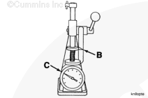
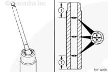
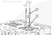
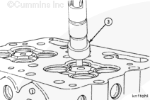
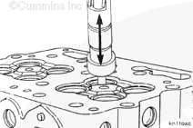
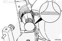
Use a valve seat grinding machine, Part Number ST-685, and valve guide arbor set, Part Number ST-663, when grinding the valve seat inserts. Install the valve guide arbor (1) in the valve guide with the arbor puller (2).
NOTE: Rotate the arbor to make sure it is correctly installed.
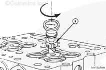
Install the eccentrimeter gauge (4), Part Number ST-685-4, on the arbor.
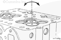
Measure the valve seat to valve guide concentricity.
Concentricity (Per 360 Degrees)
mm
in
0.09
MAX
0.0035
NOTE: If the valve seat concentricity does not meet the specifications, grind the valve seat again. If the specifications can not be met, replace the valve seat insert. Refer to Procedure 002-019 in Section 2.
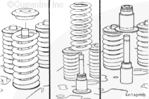
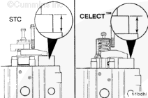
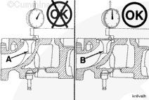
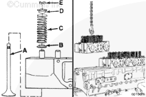
If the valve protrusion is out of specification limits, replace the old valve (A) with a new valve (B) before replacing the valve seat. If the protrusion is within specification limits with the new valve, proceed using the new valve with the old seat.
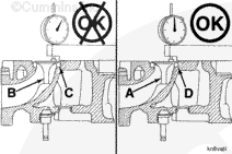
If the valve protrusion is still out of specification limits, even with a new valve (B), replace the valve seat (C) with a new valve seat (D). After replacing the valve seat, check the valve protrusion again with the old valve (A) to determine if it can be reused. If not, proceed using the new valve (B).
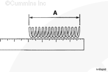
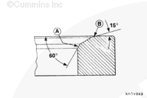
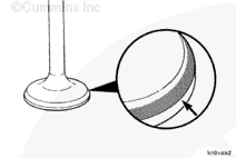
Grind area (A) with a 60 degree stone and area (B) with a 15 degree stone to center the seat on the valve face and to obtain the valve seat width limits.
When using solvents, acids, or alkaline materials for cleaning, follow the manufacturer’s recommendations for use. Wear goggles and protective clothing to reduce the possibility of personal injury.
WARNING
Wear appropriate eye and face protection when using compressed air. Flying debris and dirt can cause personal injury.
After grinding the valve seats, use a bristle brush to clean the inside diameter of the valve guides.
Use Scotch-Brite® 7448, Part Number 3823258, to clean the valve stems. Clean the carbon deposits from the valve face and head.
NOTE: The valves must be clean and free of carbon deposits before they are ground. Valves can be cleaned by the bead blasting method in the head area only.
When using solvents, acids, or alkaline materials for cleaning, follow the manufacturer’s recommendations for use. Wear goggles and protective clothing to reduce the possibility of personal injury.
WARNING
Wear appropriate eye and face protection when using compressed air. Flying debris and dirt can cause personal injury.
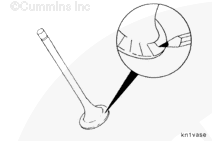
Grind the intake and exhaust valves to the angle, as illustrated.
Use solvent to clean the metal particles from the valve.
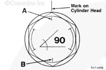
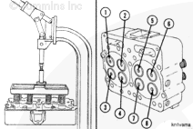
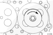
After all 12 capscrews on one head have been tightened to 298 N•m [220 ft-lb], they must be rotated in the tightening direction an additional 90 degrees. Rotate the capscrew until the mark on the cylinder head is between the next two marks joined by an arc (more than one flat and less than two flats).
When using torque plus angle, the tolerance on the 90 degree angle of rotation is one to two flats (90°± 30°). If the capscrew is rotated beyond two flats, do not loosen the capscrew.
The clamp load is still acceptable; however, rotating the capscrew beyond two flats causes additional stretch and reduces the number of reuses.
With correct tightening, the capscrew can typically be reused for the life of the engine.
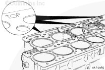
NOTE: The cylinder head must be thoroughly cleaned after using the magnetic crack detector, Part Number ST-1166, so that all iron fragments are removed.
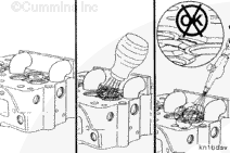
Use the magnetic crack detector, Part Number ST-1168, to find cracks in the areas around the valves the injectors.
Lightly spray the metal powder onto the combustion surface.
Use compressed air regulated to 205 kPa [30 psi] to remove excess powder from the area. The powder will remain if there are any cracks and will appear as a white line.
Inspect the cylinder head for cracks in the combustion face.
When using solvents, acids, or alkaline materials for cleaning, follow the manufacturer’s recommendations for use. Wear goggles and protective clothing to reduce the possibility of personal injury.
WARNING
Wear appropriate eye and face protection when using compressed air. Flying debris and dirt can cause personal injury.
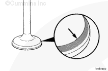
Use a lead pencil or Dykem® to mark across the valve face as illustrated. Install the valve in the valve guide.
Hold the valve against the valve seat, and rotate the valve backward and forward three or four times. Correct contact against the valve seat will break the marks on the valve face.
NOTE: Valves and valve seats that are currently machined do not require the use of lapping compound to make an air tight seal. If lapping compound is required, inspect the adjustments of the facing machine and the condition of the grinding stone.
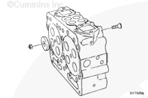
Apply cup plug sealant, Part Number 3375068, to the outside diameter of the expansion plugs.
Use expansion plug drivers to install the expansion plugs in the cylinder head. Reference table below for part numbers.
Cup Plug Size
Driver Tool Part Number
3/4-inch
3376815
1-inch
3376816
NOTE: Use the correct expansion plug driver to make sure the expansion plugs are installed to the correct depth in the cylinder head. Drive the plug until the shoulder of the driver contacts the cylinder head.
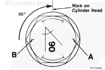
After all 12 capscrews on one head have been tightened to 298 N•m [220 ft-lb], they must be rotated in the tightening direction an additional 90 degrees. Rotate the capscrew until the mark on the cylinder head is between the next two marks joined by an arc (more than one flat and less than two flats).
When using torque plus angle, the tolerance on the 90 degree angle of rotation is one to two flats (90°± 30°). If the capscrew is rotated beyond two flats, do not loosen the capscrew.
The clamp load is still acceptable; however, rotating the capscrew beyond two flats causes additional stretch and reduces the number of reuses.
With correct tightening, the capscrew can typically be reused for the life of the engine.
Do not remove the pressure cap from a hot engine. Wait until the coolant temperature is below 50°C [120°F] before removing the pressure cap. Heated coolant spray or steam can cause personal injury.
WARNING
Coolant is toxic. Keep away from children and pets. If not reused, dispose of in accordance with local environmental regulations.
WARNING
This component or assembly weighs greater than 23 kg [50 lb]. To prevent serious personal injury, be sure to have assistance or use appropriate lifting equipment to lift this component or assembly.
Hello, I'm Jack, a diesel engine fan and a blogger. I write about how to fix and improve diesel engines, from cars to trucks to generators. I also review the newest models and innovations in the diesel market. If you are interested in learning more about diesel engines, check out my blog and leave your feedback.
View all posts by Jack

 WARNING


 CAUTION
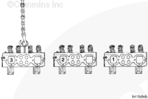


;)
;)
;)
;)
;)
;)
;)
;)
;)
;)
;)
;)
;)
;)
;)
;)
;)
;)
;)
;)
;)
;)
;)
;)
;)
;)
;)
;)
;)
;)
;)
;)
;)
;)
;)
;)
;)
;)
;)
;)
;)
;)
;)
;)
;)
;)
;)
;)
;)
;)
;)
;)
;)
;)
;)
;)
;)
;)
;)
;)
;)
;)
;)
;)
;)
;)
;)
;)
;)
;)
;)
;)
;)
;)
;)
;)
;)
;)
;)
;)
;)
;)
;)
;)
;)
;)
;)
;)
;)
;)
;)
;)
;)
;)
;)
;)
;)
;)
;)
;)
;)
;)
;)
;)
;)
;)
;)
;)
;)
;)
;)
;)
;)
;)
;)
;)
;)
;)
;)
;)
;)
;)
;)
;)
;)
;)
;)
;)
;)
;)
;)
;)
;)
;)
;)
;)
;)
;)
;)
;)
;)
;)
;)
;)
;)
;)
;)
;)
;)
;)
;)
;)
;)
;)
;)
;)
;)
;)
;)
;)
;)
;)
;)
;)
;)
;)
;)
;)
;)
;)
;)
;)
;)
;)
;)
;)
;)
;)
;)
;)
;)
;)
;)
;)
;)
;)