Centinel System – Repair Manual – 005-073   Integrated Fuel System Module (IFSM)

Preparatory Steps

TOC

With CM870


 WARNING 

Batteries can emit explosive gases. To reduce the possibility of personal injury, always ventilate the compartment before servicing the batteries. To reduce the possibility of arcing, remove the negative (-) battery cable first and attach the negative (-) battery cable last.

SMALL | MEDIUM | LARGE

CM570


 WARNING 

Batteries can emit explosive gases. To reduce the possibility of personal injury, always ventilate the compartment before servicing the batteries. To reduce the possibility of arcing, remove the negative (-) battery cable first and attach the negative (-) battery cable last.

SMALL | MEDIUM | LARGE
   

Remove

TOC

 WARNING 
This component or assembly weighs greater than 23 kg [50 lb]. To prevent serious personal injury, be sure to have assistance or use appropriate lifting equipment to lift this component or assembly.

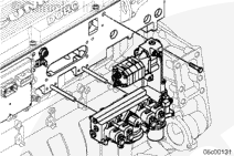
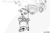
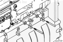
Remove two mounting capscrews from the IFSM.

Install two guide studs.

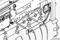
Remove the remaining capscrews, IFSM, and gasket. Discard the gasket, if damaged.

SMALL | MEDIUM | LARGE
   

Disassemble

TOC

With CM870


Remove all components:

  • Sensors
  • Regulators
  • Check valve
  • Fuel and timing actuators
  • Fuel shut-off valve
  • Gear pump (Only remove the four long capscrews, as shown in the illustration.)
  • Fuel inlet and drain fittings
  • Fuel dampers (Only remove the two top capscrews of the damper assembly, as shown in the illustration.)
  • All threaded plugs, o-rings, and gaskets.

SMALL | MEDIUM | LARGE
   

CM570


Remove all components:

  • Sensors
  • Regulators
  • Check valve
  • Fuel and timing actuators
  • Fuel shut-off valve
  • Gear pump (Only remove the four long capscrews, as shown in the illustration.)
  • Fuel inlet and drain fittings
  • Fuel dampers (Only remove the two top capscrews of the damper assembly, as shown in the illustration.)
  • All threaded plugs, o-rings, and gaskets.

SMALL | MEDIUM | LARGE
   

Clean and Inspect for Reuse

TOC

With CM870


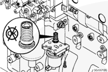
Inspect the anti-drain back valve for damage or improper sealing. Replace if necessary.

Verify that the anti-drain back valve seats properly and is free of damage or debris. If damage is found, replace the valve.

SMALL | MEDIUM | LARGE


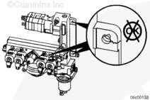
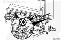
Inspect the mounting capscrew holes for cracks. Inspect the IFSM for leaks or cracks. Replace the module if cracks are found.

SMALL | MEDIUM | LARGE


Inspect the 1724 kPa [250 psi] and the 2620 kPa [380 psi] fuel regulators for debris or damage (including the spring inside the regulators). Replace the regulator if damage is found.

SMALL | MEDIUM | LARGE
   

CM570


Inspect the mounting capscrew holes for cracks.

SMALL | MEDIUM | LARGE


Remove the 1724 kPa [250 psi] fuel pressure regulator.

Inspect for debris or other damage. Replace the regulator, if necessary.

Install the fuel pressure regulator and tighten.

Torque Value:  27  n.m  [239 in-lb]

SMALL | MEDIUM | LARGE


Remove the 2206 kPa [320 psi] fuel pressure regulator.

Inspect for debris or other damage. Replace the regulator, if necessary.

Install the fuel pressure regulator and tighten.

Torque Value:  27  n.m  [239 in-lb]

SMALL | MEDIUM | LARGE


Remove the check valves located in the fuel inlet and fuel filter head.

Verify both seat properly and are free of damage or debris. Replace if necessary.

Install both check valves and tighten.

Torque Value:  17  n.m  [150 in-lb]

SMALL | MEDIUM | LARGE


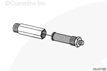
Check the inlet filter screen for debris. Clean the filter, or replace if necessary.

Install the inlet filter screen.

SMALL | MEDIUM | LARGE
   

Assemble

TOC

With CM870


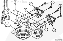
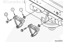
Verify the seal (1) is in the groove of the fuel control damper (2) and add Lubriplate™ multi-purpose lubricant to hold the seal in place.

Attach the fuel control damper (2) with capscrews (3) and tighten.

Torque Value:  9.5  n.m  [84 in-lb]

SMALL | MEDIUM | LARGE


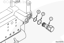
Install the o-rings (2 and 3) onto the pressure regulator (1).

Install the (2620 kPa) [380 psi] pressure regulator (1) into the IFSM housing and tighten.

Torque Value:  27  n.m  [239 in-lb]

SMALL | MEDIUM | LARGE


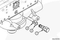
Install the o-rings (2 and 3) onto the pressure regulator (1).

Install the (1724 kPa) [250 psi] fuel pressure regulator into the IFSM housing and tighten.

Torque Value:  27  n.m  [239 in-lb]

SMALL | MEDIUM | LARGE


Install the o-ring seal (2) onto the fuel pressure sensor (1).

Install the fuel pressure sensor (1) into the IFSM housing and tighten.

Torque Value:  23  n.m  [204 in-lb]

SMALL | MEDIUM | LARGE


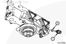
Install the o-ring seal (2) onto the fuel temperature sensor (1).

Install the fuel temperature sensor into the IFSM housing and tighten.

Torque Value:  23  n.m  [204 in-lb]

SMALL | MEDIUM | LARGE


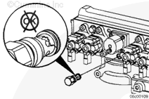
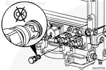
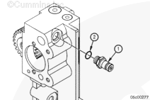
Install the o-ring (2) onto the Compuchek™ fitting (1).

Install both Compuchek™ fittings (1) into the IFSM housing and tighten.

Torque Value:  9.5  n.m  [84 in-lb]

SMALL | MEDIUM | LARGE


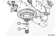
Install the o-ring (2) onto the anti-drain back valve (1).

Install the anti-drain back valve (1) into the housing and tighten.

Torque Value:  17  n.m  [150 in-lb]

SMALL | MEDIUM | LARGE


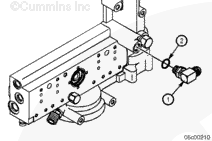
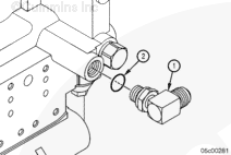
Install the o-ring (2) onto the cooling plate fuel supply fitting (1).

Install the cooling plate fuel supply fitting (1) into the housing and tighten.

Torque Value:  27  n.m  [239 in-lb]

Install the o-ring (3) onto the front face of the cooling plate fuel supply fitting.

SMALL | MEDIUM | LARGE


Install the o-ring (2) onto the fuel drain fitting (1).

Install the fuel drain fitting (1).

Turn the nut all the way to the top of the fitting.

Thread the fitting all the way into the IFSM housing, until it stops.

Turn the fitting back until the threaded end is oriented directly over the regulator.

Lock the fitting into position and tighten the locking nut.

Torque Value:  45  n.m  [33 ft-lb]

Maintain the correct orientation.

SMALL | MEDIUM | LARGE


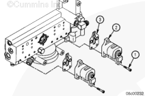
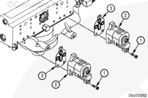
Use a small amount of Lubriplate™ multi-purpose lubricant in the grooves on the bottom of the metering actuators (2).

Install the actuator gasket (3) onto each actuator. Make sure to align each properly.

Install the actuators (2) onto the IFSM housing.

Use three capscrews (1) to mount each actuator to the housing and tighten the capscrews.

Torque Value:  15  n.m  [133 in-lb]

SMALL | MEDIUM | LARGE


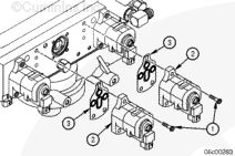
Use a small amount of Lubriplate™ multi-purpose lubricant in the grooves on the bottom of the timing actuators (2).

Install the actuator gasket (3) onto each actuator. Make sure to align each properly.

Install the actuators (2) onto the IFSM housing.

Use three capscrews (1) to mount each actuator to the housing and tighten the capscrews.

Torque Value:  15  n.m  [133 in-lb]

SMALL | MEDIUM | LARGE


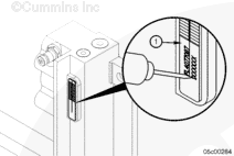
Etch the same part number of the original IFSM on the data tag (1).

Attach the tag to the housing by pressing the screws (2) into the housing.

 
SMALL | MEDIUM | LARGE


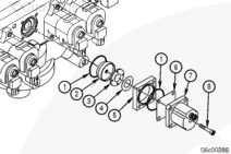
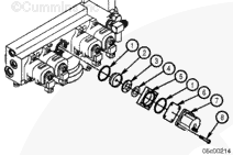
Install the seal (1) into the groove in the IFSM housing.

Place the actuator disc (2) over the seal (1), small diameter down.

Place the valve disc (3) onto the actuator disc (2) with the sealing surface down (spring pilot diameter up).

Place the valve spring (4) into the actuator housing (5) with the inside diameter on the valve disc pilot (3).

Place the actuator housing (5) over the actuator disc (2).

Install the seal (1) into the groove in the actuator housing (5).

Place the shutoff valve shield (6) over the actuator housing (5).

Align the hole pattern of the shutoff valve shield (6).

Place the solenoid (7) over the shutoff valve shield (6) taking care to align the holes and not pinch any seals. Orient the terminal facing the gear pump.

Use four capscrews (8) to attach the assembly to the housing and use an “x” pattern.

Torque Value:  5.5  n.m  [49 in-lb]

SMALL | MEDIUM | LARGE


Install the o-ring (2) onto the threaded plug (1).

Install the three threaded plugs (1) into the housing.

Torque Value:  17  n.m  [150 in-lb]

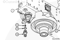
Install the o-ring (4) onto the large threaded plug (3).

Install the large threaded plug (3) into the housing.

Torque Value:  14  n.m  [124 in-lb]

SMALL | MEDIUM | LARGE


Install the o-rings (2) onto the threaded plugs (1).

Install the two threaded plugs (1) into the housing.

Torque Value:  17  n.m  [150 in-lb]

Install the o-ring (4) onto the fuel supply fitting (3).

Install the fuel supply fitting (3) into the housing.

Torque Value:  27  n.m  [239 in-lb]

SMALL | MEDIUM | LARGE


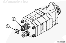
Install the o-ring (1) onto the fuel inlet fitting ( 2) from the ECM cooling plate.

Install the fitting (2) into the fuel gear pump and tighten.

Torque Value:  27  n.m  [239 in-lb]

Install the o-ring (3) onto the fuel inlet fitting (2).

SMALL | MEDIUM | LARGE


Install the o-ring (3) onto the fuel gear pump (2).

Apply Lubriplate™ multi-purpose lubricant to the o-ring (3).

Install the gasket (4) onto the gear fuel pump.

Use four capscrews (1) to install the pump to the IFSM housing.

Torque Value:  11  n.m  [97 in-lb]

SMALL | MEDIUM | LARGE


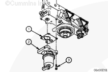
Install the lift pump gasket (1) onto the lift pump (2).

Use four capscrews (3) to install the lift pump to the housing.

Torque Value:  18  n.m  [159 in-lb]

SMALL | MEDIUM | LARGE
   

CM570


Verify the seal (1) is in the groove of the fuel control damper (2) and add Lubriplate™ multi-purpose lubricant to hold the seal in place.

Attach the fuel control damper (2) with capscrews (3) and tighten.

Torque Value:  9.5  n.m  [84 in-lb]

SMALL | MEDIUM | LARGE


Install the o-rings (2 and 3) onto the pressure regulator (1).

Install the 2206 kPa [320 psi] pressure regulator (1) into the IFSM housing and tighten.

Torque Value:  27  n.m  [239 in-lb]

SMALL | MEDIUM | LARGE


Install the o-rings (2 and 3) onto the pressure regulator (1).

Install the 1724 kPa [250 psi] fuel pressure regulator into the IFSM housing and tighten.

Torque Value:  27  n.m  [239 in-lb]

SMALL | MEDIUM | LARGE


Install the o-rings (2) onto the fuel pressure sensor (1).

Install the fuel pressure sensor (1) into the IFSM housing and tighten.

Torque Value:  23  n.m  [204 in-lb]

NOTE: Some IFSMs contain an additional fuel pressure sensor.

SMALL | MEDIUM | LARGE


Install the air bleed (2) onto the air bleed orifice into the IFSM (1) through the opening for the Compuchek™ fitting.

Torque Value:  7.9  n.m  [70 in-lb]

SMALL | MEDIUM | LARGE


Install the o-ring (2) onto the Compuchek™ fitting (1).

Install both Compuchek™ fittings (1) into the IFSM housing and tighten.

Torque Value:  9.5  n.m  [84 in-lb]

SMALL | MEDIUM | LARGE


Install the o-ring (2) onto the anti-drain back valve (1).

Install the anti-drain back valve (1) into the housing and tighten.

Torque Value:  17  n.m  [150 in-lb]

SMALL | MEDIUM | LARGE


Install the o-ring (2) onto the anti-drain back valve (1).

Install the anti-drain back valve (1) for the fuel filter into the housing and tighten.

Torque Value:  17  n.m  [150 in-lb]

SMALL | MEDIUM | LARGE


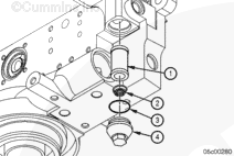
Install the filter screen (1), compression spring (2) , o-ring (3), and filter cap (4) into the housing.

Torque Value:  17  n.m  [150 in-lb]

SMALL | MEDIUM | LARGE


Install the o-ring seal (2) onto the fuel drain fitting (1).

Install the fuel drain fitting (1).

Turn the nut all the way to the top of the fitting.

Thread the fitting all the way into the IFSM housing until it stops.

Turn the fitting back until the threaded end is oriented directly over the regulator.

Lock the fitting into position and tighten the locking nut.

Torque Value:  45  n.m  [33 ft-lb]

Maintain the correct orientation.

SMALL | MEDIUM | LARGE


Use a small amount of Lubriplate™ multi-purpose lubricant in the grooves on the bottom of the metering actuators (2).

Install the actuator gasket (3) onto each actuator, making sure to align each properly.

Install the actuators (2) onto the IFSM housing.

Mount each actuator to the housing using three capscrews (1) and tighten the capscrews.

Torque Value:  15  n.m  [133 in-lb]

SMALL | MEDIUM | LARGE


Use a small amount of Lubriplate™ multi-purpose lubricant in the grooves on the bottom of the timing actuators (2).

Install the actuator gasket (3) onto each actuator, making sure to align each properly.

Install the actuators (2) onto the IFSM housing.

Mount each actuator to the housing using three capscrews (1) and tighten the capscrews.

Torque Value:  15  n.m  [133 in-lb]

SMALL | MEDIUM | LARGE


Etch the same part number of the original IFSM on the data tag (1).

Attach the tag to the housing by pressing the screws (2) into the housing.

 
SMALL | MEDIUM | LARGE


Install the seal (1) into the groove in the IFSM housing.

Place the actuator disc (2) over the seal (1), small diameter down.

Place the valve disc (3) onto the actuator disc (2) with the sealing surface down (spring pilot diameter up).

Place the valve spring (4) into the actuator housing (5) with the inside diameter on the valve disc pilot (3).

Place the actuator housing (5) over the actuator disc (2).

Install the seal (1) into the groove in the actuator housing (5).

Place the shutoff valve shield (6) over the actuator housing (5).

Align the hole pattern of the shutoff valve shield (6).

Place the solenoid (7) over the shutoff valve shield (6), taking care to align the holes and not pinch any seals. Orient the terminal facing the gear pump.

Attach the assembly to the housing using four capscrews (8) and tighten using an “x” pattern.

Torque Value:  5.5  n.m  [49 in-lb]

SMALL | MEDIUM | LARGE


Install the o-ring (2) onto the threaded plug (1).

Install the three threaded plugs (1) into the housing.

Torque Value:  17  n.m  [150 in-lb]

Install the o-ring (4) onto the large threaded plug (3).

Install the larger threaded plug (3) into the housing.

Torque Value:  14  n.m  [124 in-lb]

SMALL | MEDIUM | LARGE


Install the o-ring onto the fuel supply fitting.

Install the fuel supply fitting into the housing.

Torque Value:  27  n.m  [239 in-lb]

Install the o-ring onto the fuel inlet fitting.

SMALL | MEDIUM | LARGE


Install the o-ring (3) onto the fuel gear pump (2).

Apply Lubriplate™ multi-purpose lubricant to the o-ring (3).

Install the gasket (4) onto the gear fuel pump.

Use four capscrews (1) and install the pump to the IFSM housing.

Torque Value:  11  n.m  [97 in-lb]

SMALL | MEDIUM | LARGE


Install the lift pump gasket (1) onto the lift pump (2).

Install the lift pump to the housing using three capscrews (3).

NOTE: Some early engines were not equipped with a lift pump. These engines use a hand priming pump or they have been fitted with an auxilary lift pump.

Torque Value:  18  n.m  [159 in-lb]

SMALL | MEDIUM | LARGE
   

Install

TOC

Install two guide pins into the mounting holes on the cylinder head.

SMALL | MEDIUM | LARGE


Install a new gasket onto the guide pins.

SMALL | MEDIUM | LARGE


 WARNING 

This component or assembly weighs greater than 23 kg [50 lb]. To prevent serious personal injury, be sure to have assistance or use appropriate lifting equipment to lift this component or assembly.

Install the IFSM on the guide pins.

Install and tighten the capscrews.

Remove the guide pins.

Install and tighten the remaining capscrews.

Torque Value:  45  n.m  [33 ft-lb]

SMALL | MEDIUM | LARGE
   

Finishing Steps

TOC

With CM870


 WARNING 

Batteries can emit explosive gases. To reduce the possibility of personal injury, always ventilate the compartment before servicing the batteries. To reduce the possibility of arcing, remove the negative (-) battery cable first and attach the negative (-) battery cable last.

SMALL | MEDIUM | LARGE
   

CM570


 WARNING 
Batteries can emit explosive gases. To reduce the possibility of personal injury, always ventilate the compartment before servicing the batteries. To reduce the possibility of arcing, remove the negative (-) battery cable first and attach the negative (-) battery cable last.

SMALL | MEDIUM | LARGE
Last Modified:  03-Mar-2010