|
Battery Number 1 Voltage Low – Data Valid but Below Normal Operational Range – Moderately Severe Level
|

Overview
| CODE | REASON | EFFECT |
| Fault Code: 441 PID: P168 SPN: 168 FMI: 1/18 LAMP: Amber SRT: |
Battery Number 1 Voltage Low – Data Valid but Below Normal Operational Range – Moderately Severe Level. ECM supply voltage is below the minimum system voltage level. |
Possible reduced performance. |
|
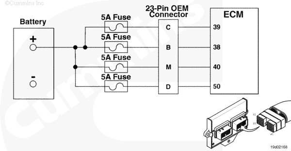
Unswitched Battery Supply Circuit |
 |
;)
;)
Circuit Description
There are four battery inputs into the OEM connectors that are unswitched battery supply to the electronic control module (ECM).
Component Location
The battery voltage circuit is located in the wiring harness.
Shop Talk
The engine will not communicate or start if the battery circuit is malfunctioning.
Cautions and Warnings
 CAUTION CAUTION To reduce the possibility of damaging a new ECM, all other active fault codes must be investigated prior to replacing the ECM. |
|
CAUTION To reduce the possibility of pin and harness damage, use the following test leads when taking a measurement: |
Troubleshooting Steps
| STEPS | SPECIFICATIONS | |
|---|---|---|
| STEP 1. | Check the fault codes. | |
| STEP 1A. Check for an inactive fault code. | Fault Code 441 inactive? | |
| STEP 2. | Check for a defective voltage source. | |
| STEP 2A. Determine if vehicle has a voltage regulator. | Voltage regulator installed? | |
| STEP 2B. Determine battery voltage. | Battery voltage between 11.5 VDC and 15.0 VDC? | |
| STEP 2C. Determine voltage on the 12 VDC side of the OEM voltage regulator. | Voltage between 11.5 VDC and 15.0 VDC? | |
| STEP 3. | Check the OEM harness. | |
| STEP 3A. Inspect the OEM harness and connector pin. | Dirty or damaged pins? | |
| STEP 3B. Check the voltage at the 23 pin OEM connector. | Voltage between 11.5 VDC and 15.0 VDC? | |
| STEP 3C. Check for an open circuit in the unswitched battery supplies in the OEM harness. | Less than 10 ohms? | |
| STEP 3D. Check for a pin to pin short in the unswitched battery supplies in the OEM harness. | Greater than 100k ohms? | |
| STEP 3E. Check for an inactive fault code. | Fault Code 441 inactive? | |
| STEP 4. | Check the ECM and engine harness. | |
| STEP 4A. Inspect the ECM and engine harness connector pins. | Dirty or damaged pins? | |
| STEP 4B. Check the voltage at the ECM. | Voltage between 11.5 VDC and 15.0 VDC? | |
| STEP 4C. Check for an open circuit in the unswitched battery supplies in the engine harness. | Less than 10 ohms? | |
| STEP 4D. Check for a pin to pin short in the unswitched battery supplies in the OEM harness. | Greater than 100k ohms? | |
| STEP 4E. Check for an inactive fault code. | Fault Code 441 inactive? | |
| STEP 5. | Clear the fault codes. | |
| STEP 5A. Disable the fault code. | Fault Code 441 inactive? | |
| STEP 5B. Clear the inactive fault codes. | All fault codes cleared? | |
Guided Step 1 – Check the fault codes.
| Guided Step 1A – Check for an inactive fault code. | |
|---|---|
Conditions
Action
|
|
|
Fault Code 441 inactive? |
|
| YES | NO |
| No Repair | No Repair |
Guided Step 2 – Check for a defective voltage regulator.
| Guided Step 2A – Determine if vehicle has a voltage regulator. | |
|---|---|
Conditions
Action
Note: If the vehicle has a 24 VDC or 36 VDC system, then it must have a voltage regulator to supply 12 VDC power to the unswitched battery pin in the ECM. |
|
|
Voltage regulator installed? |
|
| YES | NO |
| No Repair | No Repair |
| Guided Step 2B – Determine battery voltage. | |
|---|---|
Conditions
Action
|
|
|
Battery voltage between 11.5 VDC and 15.0 VDC? |
|
| YES | NO |
| No Repair |
A defective battery has been detected. Replace the defective battery or batteries. Refer to the OEM service manual. |
| Guided Step 2C – Determine the voltage on the 12 VDC side of the OEM voltage regulator. | |
|---|---|
Conditions
Action
|
|
|
Voltage between 11.5 VDC and 15.0 VDC? |
|
| YES | NO |
| No Repair |
A defective battery, battery circuit or voltage regulator has been detected. Refer to the OEM service manual. |
Guided Step 3 – Check the OEM harness.
| Guided Step 3A – Inspect the OEM harness and connector pins. | |
|---|---|
Conditions
Action
For general inspection techniques, refer to Component Connector and Pin Inspection, Procedure 019-361. |
|
|
Dirty or damaged pins? |
|
| YES | NO |
|
A defective connection has been detected in the 23 pin OEM connector. Repair the damaged pins. Repair or replace the OEM or engine harness, whichever has the damaged pins.
|
No Repair |
| Guided Step 3B – Check the voltage at the 23 pin OEM connector. | |
|---|---|
Conditions
Action
Refer to the circuit diagram or wiring diagram for connector pin identification. |
|
|
Voltage between 11.5 VDC and 15.0 VDC? |
|
| YES | NO |
| No Repair | No Repair |
| Guided Step 3C – Check the battery voltage. | |
|---|---|
Conditions
Action
Note: Check for blown or corroded fuses that are in series with the unswitched battery supplies. Refer to the circuit diagram or wiring diagram for connector pin identification. For general resistance measurement techniques, refer to the Resistance Measurements Using a Multimeter and Wiring Diagram, Procedure 019-360. |
|
|
Less than 10 ohms? |
|
| YES | NO |
| No Repair |
An open circuit has been detected in the OEM harness. Repair or replace the OEM harness.
|
| Guided Step 3D – Check for a pin to pin short in the unswitched battery supplies in the OEM harness. | |
|---|---|
Conditions
Action
Refer to the circuit diagram or wiring diagram for connector pin identification. For general resistance measurement techniques, refer to the Resistance Measurements Using a Multimeter and Wiring Diagram, Procedure 019-360. |
|
|
Greater than 100k ohms? |
|
| YES | NO |
| No Repair |
An pin to pin short has been detected in the OEM harness. Repair or replace the OEM harness.
|
| Guided Step 3E – Check for an inactive fault code. | |
|---|---|
Conditions
Action
|
|
|
Fault Code 441 inactive? |
|
| YES | NO |
| No Repair | No Repair |
Guided Step 4 – Check the ECM and engine harness.
| Guided Step 4A – Inspect the ECM and engine harness connector pins. | |
|---|---|
Conditions
Action
Refer to the circuit diagram or wiring diagram for connector pin identification. For general inspection techniques, refer to Component Connector and Pin Inspection, Procedure 019-361. |
|
|
Dirty or damaged pins? |
|
| YES | NO |
|
A defective connection has been detected in the ECM connectors or engine harness connectors. Repair the damaged pins. Repair or replace the engine harness, whichever has the damaged pins. |
No Repair |
| Guided Step 4B – Check the voltage at the ECM. | |
|---|---|
Conditions
Action
Refer to the circuit diagram or wiring diagram for connector pin identification. |
|
|
Voltage between 11.5 VDC and 15.0 VDC? |
|
| YES | NO |
| No Repair | No Repair |
| Guided Step 4C – Check for an open circuit in the unswitched battery supplies in the engine harness. | |
|---|---|
Conditions
Action
Refer to the circuit diagram or wiring diagram for connector pin identification. For general resistance measurement techniques, refer to the Resistance Measurements Using a Multimeter and Wiring Diagram, Procedure 019-360. |
|
|
Less than 10 ohms? |
|
| YES | NO |
| No Repair |
An open circuit has been detected in the engine harness. Repair the damaged pins. Repair or replace the engine harness, whichever has the damaged pins. |
| Guided Step 4D – Check for a pin to pin short in the unswitched battery supplies in the engine harness. | |
|---|---|
Conditions
Action
Refer to the circuit diagram or wiring diagram for connector pin identification. For general resistance measurement techniques, refer to the Resistance Measurements Using a Multimeter and Wiring Diagram, Procedure 019-360. |
|
|
Greater than 100k ohms? |
|
| YES | NO |
| No Repair |
An pin to pin short has been detected in the engine harness. Repair the damaged pins. Repair or replace the engine harness, whichever has the damaged pins. |
| Guided Step 4E – Check for an inactive fault code. | |
|---|---|
Conditions
Action
|
|
|
Fault Code 441 inactive? |
|
| YES | NO |
| No Repair |
Replace the ECM. Call for pre-authorization. Refer to Procedure 019-031. |
Guided Step 5 – Clear the fault codes.
| Guided Step 5A – Disable the fault code. | |
|---|---|
Conditions
Action
|
|
|
Fault Code 441 inactive? |
|
| YES | NO |
| No Repair | No Repair |
| Guided Step 5B – Clear the inactive fault codes. | |
|---|---|
Conditions
Action
|
|
|
All fault codes cleared? |
|
| YES | NO |
| No Repair | No Repair |
|
Repair complete
|
Appropriate troubleshooting charts
|