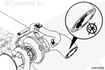
Locate and verify that the sea water inlet valve is in the full open position. If it is closed or partially closed, open the valve and recheck the engine temperature.
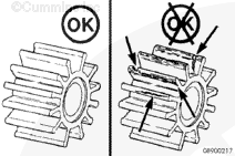
If the engine was in operation with the sea water system highly restricted due to a closed sea water inlet valve or a clogged sea water strainer, the sea water impeller must be inspected for damage.
If the hours in service of the sea water impeller is unknown, then inspection of the sea water impeller is advisable. Refer to Procedure 008-057.
If the engine continues to overheat, perform the following procedures. If the engine does not overheat at the dock, perform a sea trial and check for overheating under way.
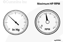
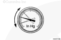
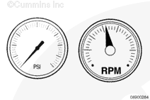
Record the sea water inlet restriction from low idle to rated speed at 500 rpm increments. This test can be conducted while the vessel is at the dock and not in gear or underway.
Refer to Procedure 018-018 for Marine engine specifications.
If the sea water inlet restriction is above specification, the source of the restriction must be found. Troubleshooting and repair of excessive sea water restriction is a boat manufacturer or boat owner responsibility. Refer to the vessel’s OEM service manual. If the inlet restriction is within the specification and the complaint can not be verified at the dock, the test must be repeated underway.
Areas to inspect for restriction are a plugged sea water strainer, sea water valve not fully open, defective hose liner in a supply hose, or debris in the inlet hose.
If the sea water inlet restriction readings fluctuate during the test, inspect the sea water supply for leaks or air intrusion. Troubleshooting and repair of excessive sea water restriction is a boat manufacturer or boat owner responsibility. Refer to the vessel’s OEM service manual. Troubleshooting and repair for sea water aeration is not covered under Cummins warranty.
Areas to inspect for a source of air are the sea water strainer inspection cover seal, sea water valve shaft seal packing, or loose hose clamps.
It is possible that aeration (gauge fluctuation) will only
occur while the vessel is underway due to the introduction of air. Refer to the vessel’s OEM service manual.
Areas to inspect for a source of aeration are water inlet scoop installed backwards, incorrect water inlet scoop, or water inlet location on the hull in aerated water flow.
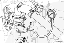
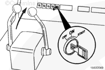
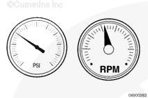
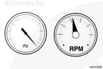
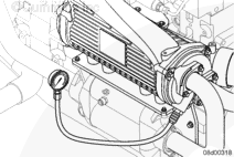
Start the engine and record the sea water outlet pressure from low idle to rated speed at 500 rpm increments. This test can be conducted while the vessel is at dock and not in gear or underway.
Refer to Procedure 018-018 for Marine engine specifications.
If the sea water pump outlet pressure is within specifications, see the Temperature Differential Test step in this procedure.
If the sea water pump outlet pressure is above the maximum specification test the individual sea water system components for excessive pressure drop as described in the Pressure Differential Test step.
Refer to Procedure 018-018 for Marine engine specifications.
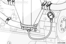
Check the sea water pressure at the inlet side of the aftercooler at the rated rpm. Record the reading. If the pressure drop between the sea water pump outlet and the aftercooler inlet exceeds the maximum specification, check or replace the fuel cooler.
Refer to Procedure 018-018 for Marine engine specifications.
If the pressure drop is within specification, check the sea water pressure at the discharge side of the aftercooler outlet. Record the reading.
If the pressure drop between the inlet side of the aftercooler exceeds the maximum, check for blockage in the lower cap area of the aftercooler. Clean or replace if necessary. Refer to Procedure 010-005.
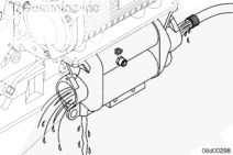
Shut off the sea water supply valve and remove the lower aftercooler sea water supply hose. Clean the debris from the aftercooler and cap. Remove the upper sea water hose and back flush the system.
Refer to Procedure 018-018 for Marine engine specifications.
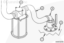
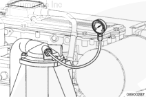
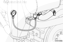
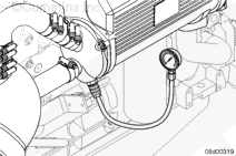
If the pressure drop between the inlet side of the aftercooler and the outlet side of the aftercooler is within specification, attach the pressure gauge to the gear oil cooler drain plug located on the outlet and check for pressure drop across the gear oil cooler.
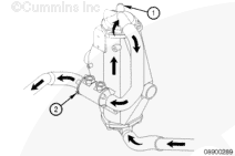
If the pressure drop between the inlet side (1) and the outlet side
(2) of the gear cooler is greater than the maximum specification, check for blockage in the gear cooler. Clean or replace if necessary. Refer to Procedure 008-041.
Refer to Procedure 018-018 for Marine engine specifications.
Install the fabricated test tool between the outlet side of the heat exchanger and the exhaust elbow. Check the pressure drop across the heat exchanger.
If the pressure drop is greater than the maximum specification, check for blockage in the heat exchanger. Clean or replace if necessary.
Refer to Procedure 018-018 for Marine engine specifications.
If the pressure drop across the heat exchanger is within specification, determine the pressure drop across the exhaust elbow (diffuser). This is done by subtracting the heat exchanger outlet pressure form the sea water pump outlet pressure. If this pressure exceeds the maximum specification, check for blockage in the exhaust elbow (diffuser) and exhaust system of the vessel. Clean or replace if necessary.
Refer to Procedure 018-018 for Marine engine specifications.
Some vessels are equipped with a sea water bypass valve to divert sea water flow from the exhaust elbow. If the valve is adjusted to the lowest system pressure, be sure the exhaust piping does not overheat under all operating conditions.
Check the sea water pressure at the inlet side of the aftercooler at the rated rpm.
Record the reading. Refer to Procedure 018-018
for marine engine specifications.
If the pressure drop between the sea water pump outlet and the aftercooler inlet exceeds the maximum specification, check for blockage or damage to the marine gear oil/fuel cooler.
If the pressure drop is within specification, check the sea water pressure at the discharge side of the aftercooler outlet. Record the reading.
If the pressure drop between the inlet side of the aftercooler exceeds the maximum, check for blockage in the lower cap area of the aftercooler. Refer to Procedure 018-018 for marine engine specifications.
Clean or replace if necessary. Refer to Procedure 010-005.
If the pressure drop between the inlet side of the aftercooler and the outlet side of the aftercooler is within specification, check for pressure drop across the engine heat exchanger.
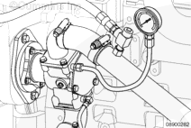
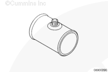
Fabricate a sea water test tool by using a 38 mm [1-1/2 in] pipe with a fitting in the center to connect a pressure gauge.
If the pressure drop across the heat exchanger is within specification, determine the pressure drop across the exhaust elbow (diffuser). This is done by subtracting the heat exchanger outlet pressure from the sea water pump outlet pressure. Refer to Procedure 018-018
for marine specifications.
If the pressure exceeds the maximum specification, check for blockage in the exhaust elbow (diffuser) and exhaust system of the vessel.
Clean or replace the elbow if necessary.
Some vessels are equipped with a sea water bypass valve to divert sea water flow from the exhaust elbow. If the valve is adjusted to the lowest system pressure, be sure the exhaust piping does not overheat under all operating conditions.
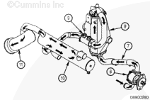
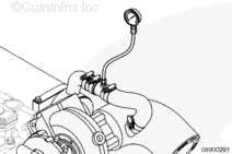
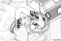
Install the sea water test tool with a temperature probe between the outlet side of the heat exchanger and the exhaust elbow (1). Operate the engine at rated rpm and load and record the temperature.
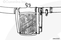
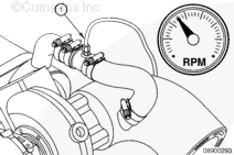
Install the temperature probe in the outlet side of the aftercooler
(1). Operate the engine at the rated rpm and load and record the temperature. If the temperature difference between the aftercooler outlet and the engine heat exchanger outlet is greater than 20°C [40°F], check the sea water pump for water flow problems. Refer to Procedure 008-057.
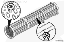
If the sea water temperature difference is less than 3°C [5°F], check the heat exchanger for possible plating to the heat exchanger core. Excessive plating or coating to the inside or outside of the cooling tubes will effect the efficiency of the heat exchanger. Refer to Procedure 008-053.
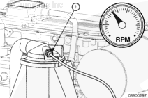
Install the temperature probe in the outlet side of the aftercooler. Operate the engine at the rated rpm and load.
Record the reading. Refer to Procedure 018-018. for marine engine specifications.
If the temperature difference between the marine gear oil/fuel cooler outlet and heat exchanger outlet, or the aftercooler outlet and the marine gear oil/fuel cooler outlet is greater than 20°C [40°F], check the sea water pump for water flow problems. Refer to Procedure 008-057.
If the sea water temperature difference is less than 3°C [5°F], check the heat exchanger and marine gear oil/fuel cooler for possible plating to the cores. Excessive plating or coating to the inside or outside of the cooling tubes will effect the efficiency.
Hello, I'm Jack, a diesel engine fan and a blogger. I write about how to fix and improve diesel engines, from cars to trucks to generators. I also review the newest models and innovations in the diesel market. If you are interested in learning more about diesel engines, check out my blog and leave your feedback.
View all posts by Jack


;)
;)
;)
;)
;)
;)
;)
;)
;)
;)
;)
;)
;)
;)
;)
;)
;)
;)
;)
;)
;)
;)
;)
;)
;)
;)
;)
;)
;)
;)
;)
;)
;)
;)
;)
;)
;)
;)
;)
;)
;)
;)
;)
;)
;)
;)
;)
;)
;)
;)
;)
;)
;)
;)
;)
;)