The intake air temperature sensor circuit is the +5-VDC supply wire (pin 21) and the signal wire (pin 25) in the sensor connector of the engine harness. Disconnect the sensor harness connector from the ECM. Check for damaged pins. Refer to Procedure 019-043.
Disconnect the intake air temperature sensor from the sensor connector of the engine harness.
To reduce the possibility of connector damage, do not use probes or leads other than Part Number 3822758. The leads must fit tightly in the connector without expanding the pins in the connector.
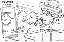
Insert a test lead into pin 21 of the sensor harness connector at the ECM. Connect the alligator clip to the multimeter probe. Touch the other multimeter probe to pin A of the intake air temperature sensor connector, wiring harness side.
Measure the resistance. The multimeter must show a closed circuit (10 ohms or less). If more than 10 ohms are measured, there is an open circuit in the +5-VDC supply wire. Repair the +5-VDC supply wire or replace the harness. Refer to Procedure 019-043.
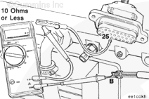
Insert a test lead into pin 25 of the sensor harness connector at the ECM. Connect the alligator clip to the multimeter probe. Touch the other multimeter probe to pin B of the sensor connector, wiring harness side.
Measure the resistance. The multimeter must show a closed circuit (10 ohms or less). If more than 10 ohms are measured, there is an open circuit in the signal wire. Repair the signal wire or replace the engine harness. Refer to Procedure 019-043.
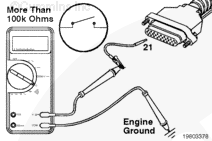
Insert a test lead into pin 21 of the sensor harness connector at the ECM. Connect the alligator clip to the multimeter probe. Touch the other multimeter probe to the engine block ground.
Make sure the intake air temperature sensor is disconnected from the wiring harness.
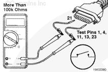
Measure the resistance. The multimeter must show an open circuit (more than 100k ohms). If the circuit is not open, there is a short circuit to ground in the +5-VDC supply wire. Repair the +5-VDC supply wire or replace the engine harness. Refer to Procedure 019-043.
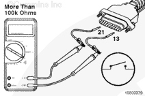
Check for a short circuit between the intake air temperature sensor +5-VDC supply wire and the return wires in the sensor connector. Connect the alligator clip of the other test lead to the other multimeter probe. Insert the test lead into return pin 13.
With the other lead still inserted in pin 21, measure the resistance.
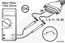
Move the lead from pin 13 to pin 1; measure the resistance. Repeat this procedure for pins 4, 11, and 23. The multimeter must show an open circuit (more than 100k ohms). If the circuit is not open, there is a short circuit between the +5-VDC supply wire and any return wire that measured less than 100k ohms. Repair or replace the engine harness. Refer to Procedure 019-043.
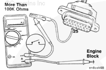
Insert a test lead into pin 25 of the sensor harness connector at the ECM. Connect the alligator clip to the multimeter probe. Touch the other multimeter probe to the engine block ground.
Make sure the intake air temperature sensor is disconnected from the sensor connector.
Measure the resistance. The multimeter must show an open circuit (more than 100k ohms). If the circuit is not open, there is a short circuit to ground in the signal wire. Repair the signal wire or replace the engine harness. Refer to Procedure 019-043.
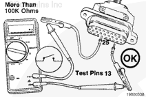
Check for a short circuit between the intake air temperature sensor signal wire and the return wires in the sensor connector. Connect the alligator clip of the other test lead to the other multimeter probe. Insert the lead into return pin 13.
With the other lead still inserted in pin 25, measure the resistance. The multimeter must show an open circuit (more than 100k ohms). If the circuit is not open, there is a short circuit between the signal wire and any return wire that measured a closed circuit. Repair or replace the engine harness. Refer to Procedure 019-043.
Repeat the above steps for the four pin numbers. Move the lead from pin 13 to pins 1, 4, 11, and 23.
Hello, I'm Jack, a diesel engine fan and a blogger. I write about how to fix and improve diesel engines, from cars to trucks to generators. I also review the newest models and innovations in the diesel market. If you are interested in learning more about diesel engines, check out my blog and leave your feedback.
View all posts by Jack


 CAUTION


;)
;)
;)
;)
;)
;)
;)
;)
;)
;)
;)
;)
;)
;)
;)
;)
;)
;)
;)
;)