A condition on M series engines where the engine will not start or is difficult to start can be caused by excessive clearance between the engine position sensor and the pickup on the back of the camshaft gear. This condition prevents the engine position sensor from sending the necessary signal to the electronic control module. The excessive clearance can be caused by a failed thrust bearing on the camshaft. Use this procedure to measure the camshaft end clearance in-chassis on M series engines without removing the front gear cover. If the end clearance is not within the specifications given, the gear cover must be removed and the cause of the excessive end clearance repaired.
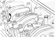
Loosen the locknut and turn out the adjusting screw on each injector and valve rocker lever. The overhead load on the camshaft must be released to allow free movement of the camshaft.
It is not necessary to remove the push rods or push tubes.
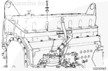
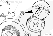
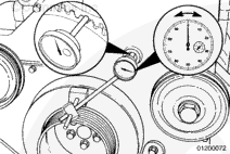
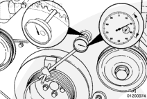
Set up a dial indicator gauge, Part Number 3376050, and extension, Part Number ST-537-4, with a magnetic base on the front of the cylinder head or vibration damper. Place the tip of the indicator on the face of the camshaft gear through the gear cover inspection hole.
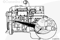
Remove the engine position sensor from the rear of the gear housing.
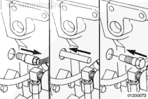
Use a rod to reach inside the gear housing through the engine position sensor mounting hole and push the camshaft gear as far as possible toward the front of the engine.
If access limits make it difficult to push the camshaft by hand, a threaded bolt (3/4 x 16) can be threaded into the hole and used as a pushing device against the back of the cam gear. The capscrew needs to have the threads ground off, approximately 25.4 mm [1 in] back from the end. Although the hole is threaded clear through the gear housing, this will make sure the capscrew does not contact anything but the camshaft gear.
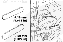
If the camshaft end clearance does not meet the above specifications, the front cover must be removed and the camshaft thrust plate inspected. Refer to Procedure 001-008.
Hello, I'm Jack, a diesel engine fan and a blogger. I write about how to fix and improve diesel engines, from cars to trucks to generators. I also review the newest models and innovations in the diesel market. If you are interested in learning more about diesel engines, check out my blog and leave your feedback.
View all posts by Jack


;)
;)
;)
;)
;)
;)
;)
;)
;)
;)
;)
;)
;)
;)
;)
;)