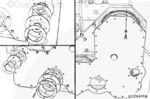
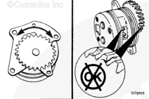
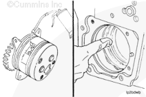
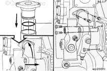
The dowel pin bore in the oil pump flange (1) must be aligned with the dowel pin in the cylinder block (2) to prevent damage to the oil pump flange during installation. Do not use the mounting capscrews to pull the oil pump into the bore. This can damage the mounting flange of the oil pump.
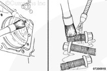
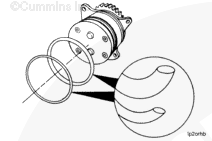
must be used to coat the threads of the three mounting capscrews to prevent air from being drawn past the capscrews during engine operation.
CAUTION
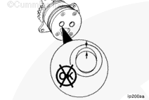
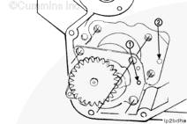
The shorter flange head capscrew must be used in the upper right-hand mounting hole (1) to prevent the idler gear from contacting the head of the capscrew and causing damage to the lubricating oil pump.
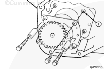
Install the three capscrews and spacers. Use the short flange head capscrew in the upper right hand mounting hole (1). Use the longer flange head capscrews and spacers in the other two holes.
Hello, I'm Jack, a diesel engine fan and a blogger. I write about how to fix and improve diesel engines, from cars to trucks to generators. I also review the newest models and innovations in the diesel market. If you are interested in learning more about diesel engines, check out my blog and leave your feedback.
View all posts by Jack


 CAUTION
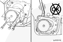


;)
;)
;)
;)
;)
;)
;)
;)
;)
;)
;)
;)
;)
;)
;)
;)
;)
;)
;)
;)
;)
;)
;)
;)
;)
;)
;)
;)