View Related Topic
Initial Check
TOC
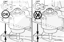
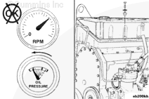
An engine equipped with an engine brake can fail to start or fail to perform properly due to one or more of the following:
Engine willnot start due to a stuck oil flow solenoid valve
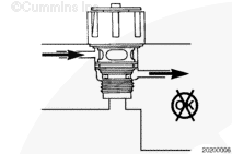
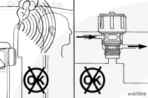
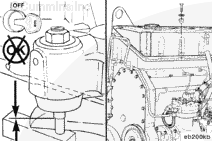
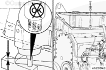
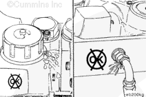
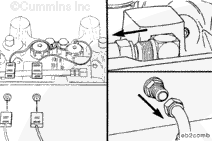
To check for a stuck solenoid valve, disconnect the electrical connection to the engine brakes and then operate the engine.
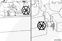
Oil supply hose loose or missing
Oil connector seal loose or missing
Upper solenoid valve seal ring missing or damaged
External oil supply hose or fitting cracked or leaking.
Remove
TOC
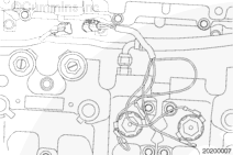
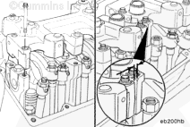
Disconnect the two electrical wires from the terminals on the inside of the rocker lever housing spacer.
Disconnect the oil supply hose connections.
Install
TOC
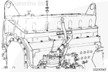
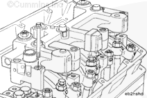
Loosen the locknuts on the slave pistons.
Make sure the slave pistons are fully retracted.
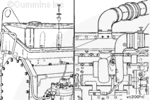
Install the rear engine brake housing on the rear rocker lever supports.
Washers arenot used with the capscrews.
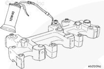
Use clean 15W-40 oil to coat the bottom side of the capscrew heads and the threads.
Install the capscrews in the rocker lever supports.
Donot tighten the capscrews.
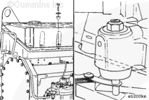
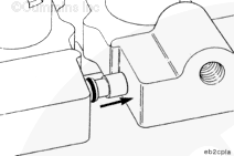
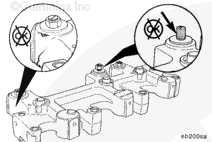
Use clean 15W-40 oil to lubricate the o-rings.
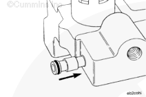
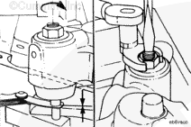
Press the connector all the way into the front housing by hand.
When installing the front housing, be sure the oil connector and o-ring are in position to be pushed into the rear housing.
Install the front engine brake housing on the front rocker lever supports.
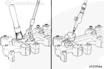
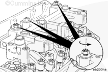
Center the oil connector between the front and rear housings before tightening the capscrews.
Tighten the capscrews in the sequence shown.
Torque Value: 81 n.m [60 ft-lb]
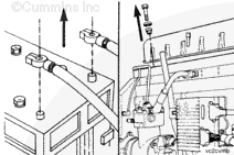
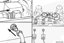
Install the oil connector supply hose and tighten the connection.
Torque Value: 19 n.m [108 in-lb]
Connect the two electrical wires to the terminals on the inside of the rocker lever housing spacer.
Last Modified: 26-Mar-2008
Published by Jack
Hello, I'm Jack, a diesel engine fan and a blogger. I write about how to fix and improve diesel engines, from cars to trucks to generators. I also review the newest models and innovations in the diesel market. If you are interested in learning more about diesel engines, check out my blog and leave your feedback.
View all posts by Jack


;)
;)
;)
;)
;)
;)
;)
;)
;)
;)
;)
;)
;)
;)
;)
;)
;)
;)
;)
;)
;)
;)
;)
;)
;)
;)
;)
;)
;)
;)
;)
;)
;)
;)
;)
;)
;)
;)
;)
;)
;)
;)
;)
;)
;)
;)
;)
;)
;)
;)