Align and connect the dynamometer. Refer to the manufacturer’s instructions for aligning and testing the engine.
NOTE: Make sure the dynamometer capacity is sufficient to permit testing at 100 percent of the engine-rated horsepower. If the capacity is not enough, the testing procedure must be modified to the restrictions of the dynamometer.
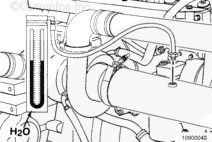
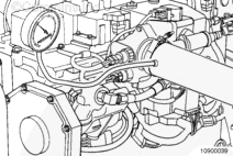
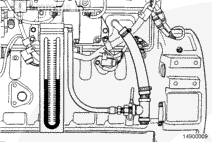
Connect a water manometer, Part Number ST-1111-3, to the turbocharger air inlet pipe to test air restriction.
NOTE: The manometer connection must be installed at a 90-degree angle to the airflow in a straight section of pipe, one pipe diameter before the turbocharger.
NOTE: A vacuum gauge, Part Number ST-434, can be used in place of the water manometer.
This component contains mercury, a chemical known to some state and federal agencies to cause birth defects or other reproductive harm. Do not dispose. Recycle in accordance with state regulations.
Connect a mercury manometer to a straight section of the exhaust piping near the turbocharger outlet to check exhaust restriction.
NOTE: A pressure gauge, Part Number ST-1273, can be used in place of the mercury manometer.
NOTE: For automotive applications, a tapped hole is provided on the inlet side of the catalyst for checking exhaust restrictions.
Do not attempt to install pipe thread fittings in plastic or rubber intake piping. Failure to do so will result in damage to threads.
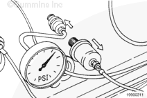
Use INSITE™ electronic service tool, if available, to monitor intake manifold pressure during the test. This eliminates the need to install a gauge as shown below.
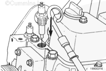
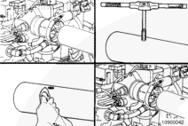
If the charge air cooler tube does not have a pipe plug and tapped hole, perform the following procedure:
Remove the charge air cooler tube from the engine.
Drill and tap a 1/8-inch pipe thread hole in the charge air cooler tube in the location shown.
Clean all metal shavings from the charge air cooler tube.
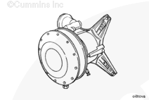
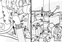
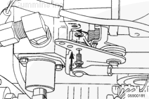
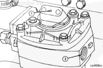
To be able to unload the compressor, connect a source of compressed air to the unloader (1). This air line must contain a valve between the source and the unloader.
NOTE: All air compressors manufactured by Cummins Inc. must be loaded during engine run-in. All air compressors must be unloaded during the engine performance check.
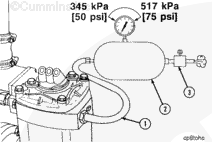
NOTE: The compressed air load in the accompanying illustration must be attached to the air compressor outlet (2).
To provide a load on the air compressor, connect an air tank (2) to the compressor outlet; use steel tubing or a high-temperature hose (1).
Install an air regulator (3) that can maintain tank air pressure of 345 kPa to 517 kPa [50 psi to 75 psi] at both the minimum and the maximum engine rpm.
Hello, I'm Jack, a diesel engine fan and a blogger. I write about how to fix and improve diesel engines, from cars to trucks to generators. I also review the newest models and innovations in the diesel market. If you are interested in learning more about diesel engines, check out my blog and leave your feedback.
View all posts by Jack





 WARNING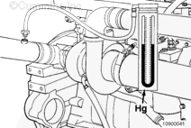
 CAUTION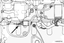

;)
;)
;)
;)
;)
;)
;)
;)
;)
;)
;)
;)
;)
;)
;)
;)
;)
;)
;)
;)
;)
;)
;)
;)
;)
;)
;)
;)
;)
;)
;)
;)
;)
;)
