Two different valve guides and valve guide seals are used on Signature™, ISX, and QSX15 engines.
Engines built prior to engine serial number 14010274 use non-grooved valve guides and small valve guide seals. These engines require the valve stem seal installer, Part Number 3163294, to be used when installing the valve guide seals.
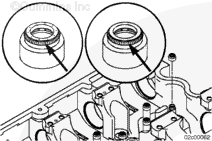
Engine serial number (ESN) 14010274 and all engines built after, use a larger valve guide seal. These seals are designed to be installed by hand without the seal driver. The new seals snap into a groove machined on the valve guide. The seals introduced into engines built after ESN 14010274 with the grooved valve guides are not compatible with engines built with the non-grooved valve guides and vice versa.
NOTE: The seals that mate with the grooved valve guides had two iterations.
Engines built from May 15, 2000 to the end of February, 2002 had separate intake and exhaust valve guide seals which were color coded. Intake valve guide seals had a brass-colored garter spring and three raised dots molded into the rubber; the exhaust valve guide seals had a silver-colored garter spring and no raised dots.
Engines built after March, 2002 had only one valve guide seal for both intake and exhaust valve guides. These seals can be used on any engines built after ESN 14010274.
Do not remove the pressure cap from a hot engine. Wait until the coolant temperature is below 50°C [120°F] before removing the pressure cap. Heated coolant spray or steam can cause personal injury.
WARNING
Coolant is toxic. Keep away from children and pets. If not reused, dispose of in accordance with local environmental regulations.
This component or assembly weighs greater than 23 kg [50 lb]. To reduce the possibility of serious personal injury, be sure to have assistance or use appropriate lifting equipment to lift this component or assembly.
Valve springs are under tension and can act as projectiles if improperly released. To reduce the possibility of eye injury, wear safety glasses with side shields. Before releasing the valve spring tension, check that the collets are properly seated.
CAUTION
Do not use an impact tool for any part of this procedure. Doing so can damage the tool and/or the engine.
NOTE: This step can be preformed either on or off-engine.
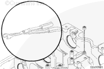
Use valve spring compressor, Part Number 4919358, to compress the valve springs.
The side of the retainer plate with the larger diameter chamfers faces down to accommodate the valve springs. Failure to position the retainer plate properly can result in damage to the engine and/or tool.
Position the compressor plate (2) over the replacer screw (1) and onto the valve springs.
Repeat the above steps for each cylinder as needed.
NOTE: It is not necessary to remove the valve spring guides on cylinder heads that have the grooved style valve guides. Valve guides that do not have the groove must have the valve spring guides removed for use of the installation tool.
NOTE: The seals that mate with the grooved valve guides had two iterations.
Engines built from May 15, 2000 to the end of February, 2002 had separate intake and exhaust valve guide seals which were color coded. Intake valve guide seals had a brass-colored garter spring and three raised dots molded into the rubber; the exhaust valve guide seals had a silver-colored garter spring and no raised dots.
Engines built after March, 2002 had only one valve guide seal for both intake and exhaust valve guides. These seals can be used on any engines built after ESN 14010274.
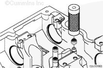
Install the intake and exhaust valve guide seals by snapping the seal by hand into the groove on the valve guide.
NOTE: Make certain the valve spring guides are removed before installing the non-grooved valve guide seals.
Use an unmodified valve seal installer, Part Number 3163294, to install the valve guide seals. The seal installer must make contact with the cylinder head when installed. This correctly locates the valve guide seal.
Valve springs are under tension and can act as projectiles if improperly released. To reduce the possibility of eye injury, wear safety glasses with side shields. Before releasing the valve spring tension, check that the collets are properly seated.
CAUTION
Do not use an impact tool for any part of this procedure. Doing so can damage the tool and/or the engine.
Use the four valve spring compressor, Part Number 4919358, to compress the valve springs.
The side of the retainer plate with the larger diameter chamfers faces down to accommodate the valve springs. Failure to position the retainer plate properly can result in damage to the engine and/or tool.
Position the compressor plate (2) over the replacer screw (1) and onto the valve springs.
If failure resulted in coolant, oil, excessive fuel or excessive black smoke entering the exhaust system, the aftertreatment system must be inspected. Refer to Procedure 014-013 in Section 14.
Operate the engine and check for leaks and proper operation.
This component or assembly weighs greater than 23 kg [50 lb]. To reduce the possibility of serious personal injury, be sure to have assistance or use appropriate lifting equipment to lift this component or assembly.
If failure resulted in coolant, oil, excessive fuel or excessive black smoke entering the exhaust system, the aftertreatment system must be inspected. Refer to Procedure 014-013 in Section 14.
Operate the engine and check for leaks and proper operation.
Hello, I'm Jack, a diesel engine fan and a blogger. I write about how to fix and improve diesel engines, from cars to trucks to generators. I also review the newest models and innovations in the diesel market. If you are interested in learning more about diesel engines, check out my blog and leave your feedback.
View all posts by Jack


 WARNING


 CAUTION


;)
;)
;)
;)
;)
;)
;)
;)
;)
;)
;)
;)
;)
;)
;)
;)
;)
;)
;)
;)
;)
;)
;)
;)
;)
;)
;)
;)
;)
;)
;)
;)
;)
;)
