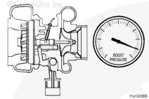
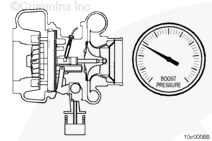
When the exhaust gas recirculation (EGR) flow is commanded, the variable geometry turbocharger closes the nozzle in the turbine housing, creating more back pressure in the exhaust manifold to force exhaust gas back into the engine.
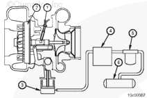
The variable geometry turbocharger functions as a standard turbocharger, with the addition of the following:
A speed sensor (1) in the bearing housing to monitor turbocharger operation
Water-cooled bearing housings (in addition to oil lubrication)
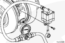
A sliding nozzle (2) is actuated by a pneumatic actuator attached to the vehicle (brake) air supply system
A pneumatic actuator (3) is operated by an air control valve (4)
On some engines, a filter and shutoff valve (5) are used in the air line between the control valve (4) and the air supply tank (6).
NOTE: A noise can be heard as air is released from the actuator (3), through the control valve (4, ) when the variable geometry turbocharger mechanism opens.
When using a steam cleaner, wear safety glasses or a face shield, as well as protective clothing. Hot steam can cause serious personal injury.
WARNING
Batteries can emit explosive gases. To reduce the possibility of personal injury, always ventilate the compartment before servicing the batteries. To reduce the possibility of arcing, remove the negative (-) battery cable first and attach the negative (-) battery cable last.
WARNING
Do not remove the pressure cap from a hot engine. Wait until the coolant temperature is below 50°C [120°F] before removing the pressure cap. Heated coolant spray or steam can cause personal injury.
WARNING
Coolant is toxic. Keep away from children and pets. If not reused, dispose of in accordance with local environmental regulations.
Steam clean the area around the turbocharger actuator and dry with compressed air.
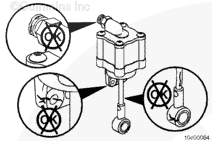
The zinc anode is a sacrificial washer that reduces the possibility of corrosion of the turbocharger cross-shaft and bushing. The failure to install will result in excessive corrosion and wear to the cross-shaft bushing.
CAUTION
The actuator maintains a spring tension on the variable geometry cross-shaft and can not be removed without releasing this tension by applying air pressure. Damage to the turbocharger can possibly result if air pressure is not applied before removing the actuator.
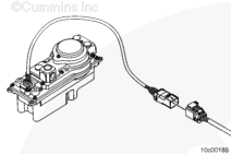
Remove the air line from the actuator if INSITE™ electronic service tool will not be used in the removal of the actuator.
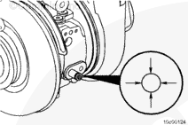
Remove the capscrew and zinc anode washer from the turbocharger cross-shaft.
Keep fingers and hands away from the actuator link to reduce the possibility of personal injury as a result of sudden movement when air is supplied.
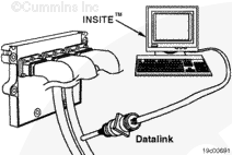
Use INSITE™ electronic service tool to override the turbocharger actuator position or apply 620 kPa [90 psi] to 827 kPa [120 psi] of regulated air pressure to the turbocharger actuator.
Remove the two capscrews holding the turbocharger actuator to the turbocharger bearing housing.
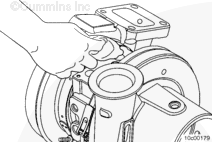
The turbocharger actuator end link to cross-shaft is a tight clearance fit. Use care to reduce the possibility of damaging the turbocharger actuator or the turbocharger cross-shaft when removing the actuator.
Remove the turbocharger actuator from the turbocharger.
Turn off the override in INSITE™ electronic service tool or remove the regulated air supply.
Remove the air line from the turbocharger actuator, if not already removed.
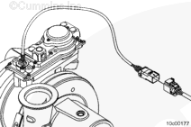
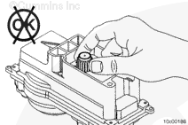
Disconnect the wiring harness from the turbocharger actuator by sliding the locking tang to the open position, then pushing down on the release lever and pulling the connection apart.
Inspect the actuator mounting bracket, rod, and body. If the actuator is bent or cracked, it must be replaced.
Inspect the bushing in the actuator rod end that attaches to the turbocharger cross-shaft for wear, scoring, or other damage. Replace the actuator if damage is found.
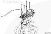
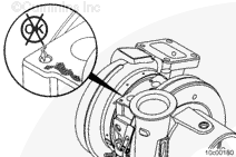
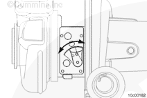
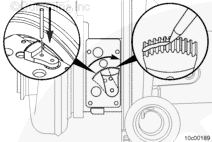
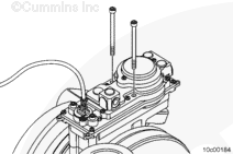
Rotate the sector gear towards the turbocharger compressor cover until it stops. The 5 mm [0.2 in] through hole in the center of the sector gear must line up with the 5 mm [0.2 in] blind hole in the bearing housing. Insert the installation pin to verify full travel in this direction.
Rotate the sector gear towards the turbocharger turbine housing until it stops.
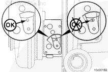
If the sector gear does not go through its entire range of motion, or the sector gear requires excessive force to move it by hand, it is necessary to replace the entire turbocharger. Refer to Procedure 010-033
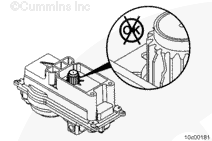
There are no serviceable parts inside the actuator, do not disassemble the actuator body.
This test can be performed with the actuator removed or installed on the turbocharger.
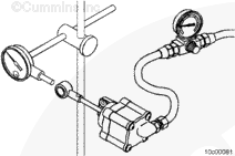
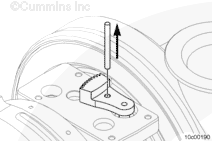
Attach a dial indicator as shown so the shaft is in line with the actuator rod.
Set the dial indicator to zero, with no air pressure applied to the actuator.
Connect clean and regulated pressurized air and a pressure gauge to the actuator. Apply a minimum of 414 kPa [60 psi] to make sure the actuator is functioning properly.
The rod must move without sticking.
Actuator Movement Range
mm
in
12
MIN
0.472
Air must not be heard leaking through a functional actuator.
Spray soapy water on the actuator housing to check for air leaks. Replace the actuator housing if leaks are found.
Replace the actuator if no movement of the actuator rod is detected, the actuator is sticking, or an air leak is found.
Keep fingers and hands away from actuator link to reduce the possibility of personal injury as a result of sudden movement when air is supplied.
If using INSITE™ electronic service tool to override the turbocharger actuator position, connect the vehicle air supply line to the turbocharger actuator.
If INSITE™ electronic service tool is not being used to remove the actuator, apply 620 kPa [90 psi] to 827 kPa [120 psi] of regulated air pressure to the turbocharger actuator.
The turbocharger actuator end link to cross-shaft is a tight clearance fit. Use care to reduce the possibility of damaging the turbocharger actuator or the turbocharger or the turbocharger cross-shaft when removing the actuator.
Install the turbocharger actuator onto the turbocharger.
If not installing new turbocharger actuator, apply Threadlocker, Part Number 3824040, onto the two capscrews holding the turbocharger actuator, before installing the capscrews onto the turbocharger bearing housing.
The zinc anode is a sacrificial washer that reduces the possibility of corrosion of the turbocharger cross-shaft and bushing. The failure to install will result in excessive corrosion and wear to the cross-shaft bushing.
Install the snap ring onto the turbocharger cross-shaft.
Apply Threadlocker, Part Number 3824040, onto the capscrew holding the zinc anode washer before installing the zinc anode washer and the capscrew.
Torque Value: 23 n.m [17 ft-lb]
Turn off the override in INSITE™ electronic service tool or remove the regulated air supply.
If not already installed, install the air line to the turbocharger actuator.
During the turbocharger actuator install test, the pinion gear on the actuator will move. Keep hands and tools away from the pinion gear during the test.
Batteries can emit explosive gases. To reduce the possibility of personal injury, always ventilate the compartment before servicing the batteries. To reduce the possibility of arcing, remove the negative (-) battery cable first and attach the negative (-) battery cable last.
In INSITE™ electronic service tool, go to the screen labeled ECM Diagnostic Tests.
From the list of tests, select VGT Electronic Actuator Installation and Calibration and select Install Actuator from the drop down menu on the main screen.
This will set the actuator pinion gear to a set position to prepare it for installation to the turbocharger.
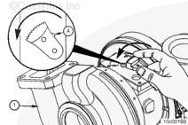
Turbocharger pre-installation instructions – grasp the sector gear by hand and rotate the sector gear toward the turbocharger compressor cover until the 5 mm [0.2 in] through hole lines up with the 5 mm [0.2 in] blind hole in the bearing housing. Use the alignment pin included in the service kit to make sure the sector gear is in the correct position prior to actuator installation.
Coat the teeth on the sector gear with the grease packet supplied in the installation kit.
NOTE: It is critical for smooth reliable operation of the actuator to use the full amount of the Cummins Turbo Technologies supplied grease.
Do not attempt to force the actuator on to the bearing housing by using the capscrews. Misalignment and damage to the actuator or turbocharger can result.
Align the actuator and gasket assembly with the turbocharger bearing housing face using the two lower screws in the bearing housing threads.
Align the actuator to the bearing housing and slide the actuator into place by hand. The actuator pinion gear and the turbocharger sector gear must engage smoothly. If not engaged smoothly, verify that the sector gear through hole and the bearing housing blind hole are aligned and try again.
If failure resulted in coolant, oil, excessive fuel or excessive black smoke entering the exhaust system, the aftertreatment system must be inspected. Refer to Procedure 014-013
Hello, I'm Jack, a diesel engine fan and a blogger. I write about how to fix and improve diesel engines, from cars to trucks to generators. I also review the newest models and innovations in the diesel market. If you are interested in learning more about diesel engines, check out my blog and leave your feedback.
View all posts by Jack
 WARNING


 CAUTION
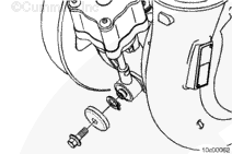


;)
;)
;)
;)
;)
;)
;)
;)
;)
;)
;)
;)
;)
;)
;)
;)
;)
;)
;)
;)
;)
;)
;)
;)
;)
;)
;)
;)
;)
;)
;)
;)
;)
;)
;)
;)
;)
;)
;)
;)
;)
;)
;)
;)
;)
;)
;)
;)