|
Engine Position Sensor Circuit – Both Signals Lost
|

Overview
| CODE | REASON | EFFECT |
| Fault Code: 115 PID: P190 SPN: 190 FMI: 2 LAMP: Red SRT: |
Engine position sensor circuit – both signals lost. |
Engine can possibly die or will |
|
Engine Position Sensor Circuit |
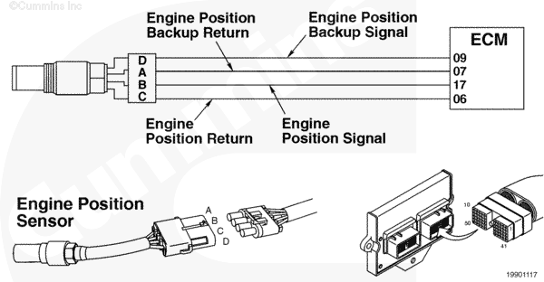 |
Circuit Description
The engine position sensor is a magnetic sensor that provides engine speed and position to the electronic control module. This sensor generates a signal from the movement of target teeth machined into the rear side of the camshaft gear.
Component Location
The engine position sensor is located in the gear housing behind the air compressor.
Refer to Procedure 100-002 (Engine Diagrams) in Section E for a detailed component location.
Shop Talk
During normal engine operation, the intake manifold is under a vacuum (less than atmospheric pressure). When the intake manifold pressure indicates a vacuum, the engine will be running. Fault Code 115 can become active with the keyswitch on and the engine RPM at zero, if the intake manifold pressure indicates a pressure that is different than expected. INSITE™ electronic service tool can be used to compare the intake manifold pressure sensor to the mixer inlet pressure sensor. These two sensors
must both be equal and read atmospheric pressure (101.3 kPa [14.7 psia] at sea level) with the keyswitch on and the engine
not running. If these are
not equal, it possibly indicates an in-range failure of the intake manifold pressure sensor. The engine will possibly
not start if this condition exists.
Check the engine position sensor for engine oil contamination. Engine oil will wick through the wires into the connector. Also check the tip of the sensor for damage, the tip can extrude out of the sensor body and contact the camshaft gear, damaging the sensor.
Cautions and Warnings
 CAUTION CAUTION To reduce the possibility of damaging a new ECM, all other active fault codes must be investigated prior to replacing the ECM. |
|
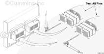
CAUTION To reduce the possibility of pin and harness damage, use the following test leads when taking a measurement: |
Troubleshooting Steps
| STEPS | SPECIFICATIONS | |
|---|---|---|
| STEP 1. | Check the fault codes. | |
| STEP 1A. Read the fault codes. | Fault Code 115 active? | |
| STEP 2. | Check the engine position sensor. | |
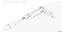
| STEP 2A. Inspect the engine harness and engine position sensor connector pins. | Dirty or damaged pins? | |
| STEP 2B. Check the resistance of the sensor. | 1000 to 2000 ohms? | |
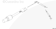
| STEP 2C. Check for a short circuit to ground. | Greater than 100k ohms? | |
| STEP 2D. Inspect the sensor for damage. | Damaged sensor? | |
| STEP 2E. Read the fault codes. | Fault Code 115 active? | |
| STEP 3. | Check the engine harness. | |
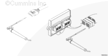
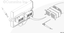
| STEP 3A. Inspect the engine harness and ECM connector pins. | Dirty or damaged pins? | |
| STEP 3B. Check for an open circuit. | Less than 10 ohms? | |
| STEP 3C. Check for a short circuit to ground. | Greater than 100k ohms? | |
| STEP 3D. Check for a short circuit from pin to pin. | Greater than 100k ohms? | |
| STEP 4. | Clear the fault codes. | |
| STEP 4A. Disable the fault code. | Fault Code 115 inactive? | |
| STEP 4B. Clear the inactive fault codes. | All fault codes cleared? | |
Guided Step 1 – Check the fault codes.
| Guided Step 1A – Read the fault codes. | |
|---|---|
Conditions
ActionRead the fault codes. Use INSITE™ electronic service tool to read the fault codes. |
|
|
Fault Code 115 active? |
|
| YES | NO |
| No Repair | No Repair |
Guided Step 2 – Check the engine position sensor.
| Guided Step 2A – Inspect the engine harness and engine position sensor connector pins. | |
|---|---|
Conditions
ActionInspect the engine harness and engine position sensor connector pins for the following:
|
|
|
Dirty or damaged pins? |
|
| YES | NO |
|
Repair the damaged pins. Repair or replace the engine harness, or replace the sensor, whichever has the damaged pins.
|
No Repair |
| Guided Step 2B – Check the resistance of the sensor. | ||
|---|---|---|
Conditions
ActionCheck the resistance of the sensor.
Refer to the circuit diagram or wiring diagram for connector pin identification. |
|
|
|
1000 to 2000 ohms? |
||
| YES | NO | |
| No Repair |
Replace the sensor. |
|
| Guided Step 2C – Check for a short circuit to ground. | ||
|---|---|---|
Conditions
ActionCheck for a short circuit to ground.
Refer to the circuit diagram or wiring diagram for connector pin identification. |
|
|
|
Greater than 100k ohms? |
||
| YES | NO | |
| No Repair |
Replace the sensor. |
|
| Guided Step 2D – Inspect the sensor for damage. | |
|---|---|
Conditions
ActionInspect the engine position sensor for the following:
|
|
|
Damaged sensor? |
|
| YES | NO |
|
Replace the sensor. |
No Repair |
| Guided Step 2E – Read the fault codes. | |
|---|---|
Conditions
ActionRead the fault codes.
|
|
|
Fault Code 115 active? |
|
| YES | NO |
| No Repair | No Repair |
Guided Step 3 – Check the engine harness.
| Guided Step 3A – Inspect the engine harness and ECM connector pins. | |
|---|---|
Conditions
ActionInspect the engine harness and ECM connector pins for the following:
|
|
|
Dirty or damaged pins? |
|
| YES | NO |
|
Repair the damaged pins. Replace the engine harness, or replace the ECM, whichever has the damaged pins.
|
No Repair |
| Guided Step 3B – Check for an open circuit. | ||
|---|---|---|
Conditions
ActionCheck for an open circuit.
|
|
|
|
Less than 10 ohms? |
||
| YES | NO | |
| No Repair |
Repair the engine harness.
|
|
| Guided Step 3C – Check for a short circuit to ground. | ||
|---|---|---|
Conditions
ActionCheck for a short circuit to ground.
|
|
|
|
Greater than 100k ohms? |
||
| YES | NO | |
| No Repair |
Repair or replace the engine harness.
|
|
| Guided Step 3D – Check for a short circuit from pin to pin. | ||
|---|---|---|
Conditions
ActionCheck for a short circuit from pin-to-pin.
|
|
|
|
Greater than 100k ohms? |
||
| YES | NO | |
| No Repair |
Repair or replace the engine harness.
|
|
;)
;)
;)
;)
;)
;)
;)
;)
;)
;)
;)
;)
Guided Step 4 – Clear the fault codes.
| Guided Step 4A – Disable the fault code. | |
|---|---|
Conditions
ActionDisable the fault code.
|
|
|
Fault Code 115 inactive? |
|
| YES | NO |
| No Repair |
Return to the troubleshooting seps or contact a Cummins® Authorized Repair Location if all steps have been completed and checked again. |
| Guided Step 4B – Clear the inactive fault codes. | |
|---|---|
Conditions
ActionClear the inactive fault codes.
|
|
|
All fault codes cleared? |
|
| YES | NO |
| No Repair |
Troubleshoot any remaining active fault codes. |
|
Repair complete
|
Appropriate troubleshooting charts
|