|
Sensor Supply Voltage 5 Volt (1) – Shorted High
|

Overview
| CODE | REASON | EFFECT |
| Fault Code: 386 PID: S232 SPN: 1079 FMI: 3 LAMP: Amber SRT: |
Sensor Supply Voltage 5 Volt (1) – Shorted High. High voltage detected on sensor supply number 1 circuit. |
Possible reduced performance. |
|
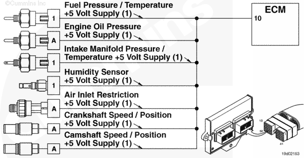
Sensor Supply Voltage 5 Volt (1) |
 |
;)
;)
Circuit Description
This circuit is the voltage supply for the intake manifold pressure/temperature sensor; the secondary fuel pressure/temperature sensor, the humidity sensor, the air inlet restriction pressure sensor, the camshaft position sensor, the crankshaft position sensor, and the oil pressure sensor.
Component Location
The sensor supply voltage 5 Volt (1) circuit is contained in the engine wiring harness.
Shop Talk
The voltage supplies for the L Gas Plus engines are broken up into 1, 2, and 4 and are shown as such on the wiring diagram.
Cautions and Warnings
 CAUTION CAUTION To reduce the possibility of damaging a new ECM, all other active fault codes must be investigated prior to replacing the ECM. |
|
CAUTION To reduce the possibility of pin and harness damage, use the following test lead when taking a measurement: |
Troubleshooting Steps
| STEPS | SPECIFICATIONS | |
|---|---|---|
| STEP 1. | Check the fault codes. | |
| STEP 1A. Check for an inactive fault code. | Fault Code 386 inactive? | |
| STEP 2. | Check the ECM and engine harness. | |
| STEP 2A. Inspect the ECM and engine harness connector pins. | Dirty or damaged pins? | |
| STEP 2B. Check for a pin to pin short circuit in the engine harness. | Greater than 100k ohms? | |
| STEP 2C. Check for an inactive fault code. | Fault Code 386 inactive? | |
| STEP 3. | Clear the fault codes. | |
| STEP 3A. Disable the fault code. | Fault Codes 386 inactive? | |
| STEP 3B. Clear the inactive fault codes. | All fault codes cleared? | |
Guided Step 1 – Check the fault codes.
| Guided Step 1A – Check for an inactive fault code. | |
|---|---|
Conditions
Action
|
|
|
Fault Codes 386 inactive? |
|
| YES | NO |
| No Repair | No Repair |
Guided Step 2 – Check the ECM and engine harness.
| Guided Step 2A – Inspect the ECM and engine harness connector pins. | |
|---|---|
Conditions
Action
For general inspection techniques, refer to Component Connector and Pin Inspection, Procedure 019-361. |
|
|
Dirty or damaged pins? |
|
| YES | NO |
|
A defective connection has been detected in the ECM engine connector or the engine harness connector. Repair the damaged pins. Repair or replace the engine harness, whichever has the damaged pins. |
No Repair |
| Guided Step 2B – Check for a pin to pin short circuit in the engine harness. | |
|---|---|
Conditions
Action
Refer to the circuit diagram or wiring diagram for connector pin identification. For general resistance measurement techniques, refer to the Resistance Measurements Using a Multimeter and Wiring Diagram, Procedure 019-360. |
|
|
Greater than 100k ohms? |
|
| YES | NO |
| No Repair |
A pin to pin short circuit on the sensor supply number 1 line has been detected in the engine harness. Repair the damaged pins. Repair or replace the engine harness, whichever has the damaged pins. |
| Guided Step 2C – Check for an inactive fault code. | |
|---|---|
Conditions
Action
|
|
|
Fault Codes 386 inactive? |
|
| YES | NO |
| No Repair |
Replace the ECM. Call for pre-authorization. Refer to Procedure 019-031. |
Guided Step 3 – Clear the fault codes.
| Guided Step 3A – Disable the fault code. | |
|---|---|
Conditions
Action
|
|
|
Fault Code 386 inactive? |
|
| YES | NO |
| No Repair | No Repair |
| Guided Step 3B – Clear the inactive fault codes. | |
|---|---|
Conditions
Action
|
|
|
All fault codes cleared? |
|
| YES | NO |
| No Repair | No Repair |
|
Repair complete
|
Appropriate troubleshooting charts
|