 |
Engine Performance Troubleshooting Tree – Signature™ and ISX CM870

Symptoms
- Engine Acceleration or Response Poor
- Cranking Fuel Pressure is Low
- Engine Operating Fuel Pressure is Low
- Engine Difficult to Start or Will Not Start (Exhaust Smoke)
- Engine Difficult to Start or Will Not Start (No Exhaust Smoke)
- Engine Run On
- Engine Power Output Low
- Engine Runs Rough at Idle
- Engine Runs Rough or Misfires
- Engine Speed Surges at Low or High Idle
- Engine Speed Surges Under Load or in Operating Range
- Smoke, Black – Excessive
- Smoke, White – Excessive
- Engine Shuts Off or Dies Unexpectedly or Dies During Deceleration
- Engine Starts But Will Not Keep operating
- Engine Will Not Reach Rated Speed (rpm).
How To Use This Tree
This symptom tree can be used to troubleshoot all performance based symptoms listed above. Start by performing Step 1 troubleshooting. Step 2 asks a series of questions and will provide a list of troubleshooting steps to perform depending on the symptom. Perform the list of troubleshooting in the sequence shown in the Specifications/Repair section of the tree.
Shop Talk
Prior to operating INSITE™ electronic service tool EGR Valve and EGR Valve/Turbocharger Operational Test, the ECM Calibration Software Phase can possibly need to be updated to the latest Software Phase. The ECM Calibration Phase Software can be checked in INSITE™ electronic service tool, under ‘Features and Parameters’. Expand the selection for ‘System ID and Dataplate’and go to ‘Calibration Information’. If the Software Phase is earlier than shown below, calibrate the ECM, use the January 2006 INCAL™ CD-ROM, or later. Engines with the Software Phase listed below or later do not require a calibration.
ISX engines with CM870 (engines built after January 2004) require Software Phase 06050302.
ISX engines with CM870 (engines built before January 2004) require no changes at this time.
This is a warrantable calibration change.
Troubleshooting Steps
| STEPS | SPECIFICATIONS | |
|---|---|---|
| STEP 1. | Perform basic troubleshooting procedures. | |
| STEP 1A. Check for active fault codes or high counts of inactive fault codes. | Active fault codes or high counts of inactive fault codes? | |
| STEP 1B. Perform basic troubleshooting checks. | All steps have been verified to be correct? | |
| STEP 2. | Determination of engine symptom. | |
| STEP 2A. Low power, poor acceleration, or poor response. | Is the engine symptom low power, poor acceleration, or poor response? | |
| STEP 2B. Engine misfire. | Is the engine symptom Engine Runs Rough or Misfires? | |
| STEP 2C. Excessive black smoke. | Is the engine symptom Excessive Black Smoke? | |
| STEP 2D. Excessive white smoke. | Is the engine symptom Excessive White Smoke and the engine is using coolant? | |
| STEP 2D-1. Excessive white smoke. | ||
| STEP 2E. Engine speed surge or engine speed unstable. | Is the engine symptom Engine Speed Surge or Engine Speed Unstable? | |
| STEP 2F. Engine will not start or difficult to start. | Is the symptom Engine Difficult to Start or Will Not Start? | |
| STEP 2G. Engine stalls or shuts off unexpectedly. | Is the symptom Engine Stalls or Shuts Off Unexpectedly? | |
| STEP 2H. Engine run on or will not shut down. | Is the engine symptom Engine Run On or Slow to Shut Down after operated at high idle for 1 minute then keyed OFF? | |
| STEP 3. | No-start troubleshooting procedures. | |
| STEP 3A. Verify the fuel system has been primed. | Has the fuel system properly primed? | |
| STEP 3B. Check fuel shutoff valve voltage. | Is the fuel shutoff valve voltage greater than 11-VDC? | |
| STEP 3B-1. Check ECM keyswitch voltage. | ||
| STEP 3B-2. Check the fuel shutoff valve wire. | ||
| STEP 3B-3. Check the ECM power and ground. | ||
| STEP 3C. Check fuel shutoff valve resistance. | Is the fuel shutoff solenoid resistance 1 to 5 ohms for 6-VDC solenoids, 6 to 15 ohms for 12-VDC solenoids, 24 to 50 ohms for 24-VDC solenoids, 42 to 80 ohms for 32-VDC solenoids, 46 to 87 ohms for 36-VDC solenoids, 92 to 145 ohms for 48-VDC solenoids, 315 to 375 ohms for 74-VDC solenoids, 645 to 735 ohms for 115-VAC solenoids? | |
| STEP 3D. Check fuel shutoff valve actuator. | Debris or damage found on the valve disc, valve seat, or actuator disc? | |
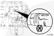
| STEP 3E. Check for correct priming pump operation, if equipped. | Does the lift pump operate after turning the keyswitch ON? | |
| STEP 3E-1. Check priming pump pressure. | ||
| STEP 3F. Check for coolant in the EGR transfer tube. | Is coolant present in the crossover tube? | |
| STEP 4. | Fuel system checks. | |
| STEP 4A. Verify the fuel system has been primed. | Has the fuel system been properly primed? | |
| STEP 4B. Check for air in the fuel. | Are air bubbles visible in the coil of clear tubing? | |
| STEP 4C. Check fuel inlet restriction. | Is fuel inlet restriction less than the specifications? | |
| STEP 4D. Check drain line restriction. | Is fuel drain line restriction less than 229 mm-Hg [9 in-Hg]? | |
| STEP 4E. Check rail fuel pressure. | Does the rail fuel pressure meet the specification? | |
| STEP 4E-1. Check the pressure side fuel filter restriction. | ||
| STEP 4E-2. Check 1724 kPa [250 psi] pressure regulator. | ||
| STEP 4E-3. Check 2206 kPa [320 psi] or 2620 kPa [380 psi] pressure regulator. | ||
| STEP 5. | Injector and Actuator Diagnostics. | |
| STEP 5A. Perform the injector check valve leak test. | Did the injector leak test detect a leaking injector? | |
| STEP 5B. Perform INSITE™ electronic service tool Cylinder Performance Test. | Does performing INSITE™ electronic service tool Cylinder Performance Test isolate to a single malfunctioning injector? | |
| STEP 5B-1. Perform INSITE™ electronic service tool Cylinder Performance Test at 600 rpm. | ||
| STEP 5B-2. Perform INSITE™ electronic service tool Cylinder Performance Test at 700 rpm. | ||
| STEP 5B-3. Perform INSITE™ electronic service tool Cylinder Performance Test at 800 rpm. | ||
| STEP 5C. Perform INSITE™ electronic service tool Cylinder Cutout Test. | Do all cylinders pass the cylinder cutout test? | |
| STEP 5C-1. Perform INSITE™ electronic service tool Cylinder Cutout Test on both injector banks. | ||
| STEP 5C-2. Perform INSITE™ electronic service tool Cylinder Cutout Test. | ||
| STEP 5C-3. Verify overhead adjustments are correct for the suspected malfunctioning injector. | ||
| STEP 5D. Swap the front and rear metering actuators. | Does the malfunctioning bank follow the metering actuator? | |
| STEP 5E. Swap the front and rear timing actuators. | Does the malfunctioning bank follow the timing actuator? | |
| STEP 6. | Air handling diagnostic checks. | |
| STEP 6A. Start the engine and read the fault codes. | Active fault codes? | |
| STEP 6B. Check the air intake system for leaks. | Leaks found? | |
| STEP 6C. Check air intake restriction. | Restriction greater than 635 mm-H2O [25 in-H2O] for a used air filter or 254 mm-H2O [10 in-H2O] for a new filter? | |
| STEP 6D. Inspect the charge-air cooler. | Problems found with the charge-air cooler? | |
| STEP 6E. Check exhaust restriction. | Restriction between 518 mm-H2O [20.4 in-H2O] or 38 mm-Hg [1.5 in-Hg] and 1036 mm-H2O [40.8 in-H2O] or 76 mm-Hg [3.0 in-Hg]? | |
| STEP 6F. Inspect the turbocharger blades for damage. | Damage found on turbocharger blades? | |
| STEP 6G. Determine turbocharger type. | Is the turbocharger a variable geometry turbocharger? | |
| STEP 6H. Check the variable geometry actuator rod for correct travel. | Does the turbocharger actuator rod extend between 10 and 12 mm [0.394 and 0.472 in]? | |
| STEP 6H-1. Check for air leaks and inspect air lines. | ||
| STEP 6D-2. Check the engine and vehicle grounds. | ||
| STEP 6D-3. Check for air pressure at the turbocharger control valve outlet. | ||
| STEP 6H-4. Check for air pressure at the turbocharger control valve outlet. | ||
| STEP 6H-5. Check for correct turbocharger actuator travel. | ||
| STEP 6H-6. Check for air pressure at the turbocharger control shutoff valve outlet. | ||
| STEP 6H-7. Check for air pressure at the turbocharger control shutoff valve inlet. | ||
| STEP 6H-8. Check for plugged turbocharger control shutoff valve filter. | ||
| STEP 6I. Perform INSITE™ electronic service tool EGR Valve/Turbocharger Operational Test. | Does the Turbocharger Operational Test pass? | |
| STEP 6E-1. Check the engine and vehicle grounds. | ||
| STEP 6J. Inspect the wastegate actuator hose. | Holes or cracks found in the wastegate actuator hose? | |
| STEP 6K. Inspect the wastegate actuator rod for travel. | Does the wastegate actuator rod move? | |
| STEP 6G-1. Inspect wastegate actuator rod for travel. | ||
| STEP 6L. Measure resistance of the four-stage wastegate controllers, if equipped. | Are the wastegate controller solenoid resistances between 7.0 and 8.0 ohms? | |
| STEP 6M. Inspect four-stage wastegate controller, if equipped. | Damage or debris found on the valve disc, valve seat, or actuator disc? | |
| STEP 7. | Check EGR valve for proper operation. | |
| STEP 7A. Check for air leaks in the EGR system. | Air leaks found in the EGR connection tubing? | |
| STEP 7B. Check the repair history. | Is there a record of the poppet head missing? | |
| STEP 7C. Perform EGR Valve Test. | Does the EGR Valve Test pass? | |
| STEP 8. | Verify electronic features are operating correctly. | |
| STEP 8A. Verify accelerator pedal travel. | Does the Accelerator Pedal read 0 when the accelerator is released and 100 percent when the accelerator is depressed? | |
| STEP 8B. Monitor vehicle speed. | Does the vehicle speed read 0 when the vehicle is not moving? | |
| STEP 8C. Verify electronic feature settings are correct. | Are the electronic features set correctly? | |
| STEP 8D. Check the barometric pressure sensor reading. | Is the barometric pressure sensor reading in INSITE™ electronic service tool within 5 percent of the present local barometric pressure reading? | |
| STEP 9. | Perform base engine mechanical checks. | |
| STEP 9A. Verify overhead adjustments are correct. | Overhead settings within the reuse limits? | |
| STEP 9B. Verify engine brake adjustment. | Engine brake settings within the reuse limits? | |
| STEP 9C. Measure turbocharger axial and radial clearance. | Axial and radial clearances within specification? | |
| STEP 9D. Verify engine blowby is within specification. | Engine blowby measurements within specification? | |
| STEP 9E. Verify injection timing is correct. | Injection timing within specification? | |
| STEP 9F. Check for a damaged vibration damper. | Vibration damper damaged or out of specification? | |
| STEP 10. | Check the EGR differential pressure sensor and exhaust gas pressure sensor tubes. | |
| STEP 10A. Check the EGR differential pressure tubes for cracks, restrictions, or leaks. | Cracks, restrictions, or leaks present? | |
| STEP 10B. Check the exhaust gas pressure sensor tubes for cracks, restrictions, or leaks. | Cracks, restrictions, or leaks present? | |
Guided Step 1 – Perform basic troubleshooting procedures.
| Guided Step 1A – Check for active fault codes or high counts of inactive fault codes. | |
|---|---|
Conditions
ActionCheck for active fault codes or high counts of inactive fault codes.
|
|
|
Active fault codes or high counts of inactive fault codes? |
|
| YES | NO |
| No Repair | No Repair |
|
Go to appropriate fault code troubleshooting tree
|
|
| Guided Step 1B – Perform basic troubleshooting checks. | |
|---|---|
Conditionsn/a ActionThe following items must be checked or verified before continuing:
|
|
|
All steps have been verified to be correct? |
|
| YES | NO |
| No Repair |
Correct the condition and verify complaint is no longer present after repair. |
|
Repair complete
|
|
Guided Step 2 – Determination of engine symptom.
| Guided Step 2A – Low power, poor acceleration, or poor response. | |
|---|---|
Conditionsn/a ActionInterview the driver and verify the complaint. n/a |
|
|
Is the engine symptom low power, poor acceleration, or poor response? |
|
| YES | NO |
|
Perform the troubleshooting steps in the recommended order listed below:
|
No Repair |
|
Perform the troubleshooting steps suggested in the repair procedure
|
|
| Guided Step 2B – Engine misfire. | |
|---|---|
Conditionsn/a ActionInterview the driver and verify the complaint. n/a |
|
|
Is the engine symptom Engine Runs Rough or Misfires? |
|
| YES | NO |
|
Perform the troubleshooting steps in the recommended order listed below:
|
No Repair |
|
Perform the troubleshooting steps suggested in the repair procedure
|
|
| Guided Step 2C – Excessive black smoke. | |
|---|---|
Conditionsn/a ActionInterview the driver and verify the complaint. n/a |
|
|
Is the engine symptom Excessive Black Smoke? |
|
| YES | NO |
|
Perform the troubleshooting steps in the recommended order listed below:
|
No Repair |
|
Perform the troubleshooting steps suggested in the repair procedure
|
|
| Guided Step 2D – Excessive white smoke. | |
|---|---|
Conditionsn/a ActionInterview the driver and verify the complaint. n/a |
|
|
Is the engine symptom Excessive White Smoke and the engine is using coolant? |
|
| YES | NO |
|
Perform the troubleshooting steps in the recommended order listed below:
|
No Repair |
|
Perform the troubleshooting steps suggested in the repair procedure
|
|
| Guided Step 2D-1 – Excessive white smoke. | |
|---|---|
Conditionsn/a ActionInterview the driver and verify the complaint. n/a |
|
|
Is the engine symptom Excessive White Smoke and the engine is not using coolant? |
|
| YES | NO |
|
Perform the troubleshooting steps in the recommended order listed below:
|
No Repair |
|
Perform the troubleshooting steps suggested in the repair procedure
|
|
| Guided Step 2E – Engine speed surge or engine speed unstable. | |
|---|---|
Conditionsn/a ActionInterview the driver and verify the complaint. n/a |
|
|
Is the engine symptom Engine Speed Surge or Engine Speed Unstable? |
|
| YES | NO |
|
Perform the troubleshooting steps in the recommended order listed below:
|
No Repair |
|
Perform the troubleshooting steps suggested in the repair procedure
|
|
| Guided Step 2F – Engine will not start or difficult to start. | |
|---|---|
ConditionsNone ActionInterview the driver to verify the complaint. n/a |
|
|
Is the symptom Engine Difficult to Start or Will Not Start? |
|
| YES | NO |
|
Perform the steps that pertain to difficult to start or will not start concerns per the troubleshooting steps in the recommended order listed below:
|
No Repair |
|
Perform the troubleshooting steps suggested in the repair procedure
|
|
| Guided Step 2G – Engine stalls or shuts off unexpectedly. | |
|---|---|
ConditionsNone ActionInterview the driver to verify the complaint. n/a |
|
|
Is the symptom Engine Stalls or Shuts Off Unexpectedly? |
|
| YES | NO |
|
Perform the steps that pertain to stalls or shuts off unexpectedly per the troubleshooting steps in the recommended order listed below:
|
No Repair |
|
Perform the troubleshooting steps suggested in the repair procedure
|
|
| Guided Step 2H – Engine run on, or will not shut down | |
|---|---|
ConditionsNone ActionInterview the driver and verify the complaint. n/a |
|
|
Is the engine symptom Engine Run On or Slow to Shut Down after operated at high idle for 1 minute then keyed OFF? |
|
| YES | NO |
|
Perform the troubleshooting steps in the recommended order listed below:
|
No Repair |
|
Perform the troubleshooting steps suggested in the repair procedure
|
Return to the appropriate symptom tree
|
Guided Step 3 – No-start troubleshooting procedures.
| Guided Step 3A – Verify the fuel system has been primed. | |
|---|---|
Conditions
ActionIf entering this tree after a component has been replaced in the fuel system, or after the engine was run out of fuel, verify the fuel system has been properly primed before proceeding.
|
|
|
Has the fuel system been properly primed? |
|
| YES | NO |
| No Repair |
Prime the fuel system.
|
|
Repair complete
|
|
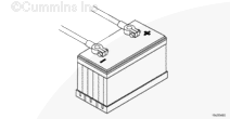
| Guided Step 3B – Check fuel shutoff valve voltage. | ||
|---|---|---|
Conditions
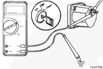
ActionMeasure the voltage from the fuel shutoff valve post to engine block ground. n/a |
|
|
|
Is the fuel shutoff valve voltage greater than 11-VDC? |
||
| YES | NO | |
| No Repair | No Repair | |
| Guided Step 3B-1 – Check ECM keyswitch voltage. | ||
|---|---|---|
Conditions
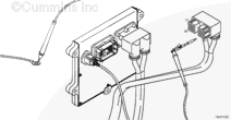
ActionMeasure the voltage from the keyswitch input SIGNAL wire of the OEM harness to engine block ground. n/a |
|
|
|
Is the keyswitch voltage equal to battery voltage? |
||
| YES | NO | |
| No Repair |
Repair or replace the OEM power harness, keyswitch, or check the battery connections. Use the following procedure in the Troubleshooting and Repair Manual, CM870 Electronic Control System Signature™ and ISX Engines, Bulletin 4021334. Refer to Procedure 019-064 in Section 19. |
|
|
Repair complete
|
||

| Guided Step 3B-2 – Check the fuel shutoff valve wire. | ||
|---|---|---|
Conditions
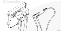
ActionMeasure the resistance from the fuel shutoff valve SIGNAL pin in the ECM connector to the fuel shutoff valve eyelet. Use the circuit diagram or wiring diagram for connector pin identification. Use the following procedure for general resistance measurement techniques. Use the following procedure in the Troubleshooting and Repair Manual, CM870 Electronic Control System Signature™ and ISX Engines, Bulletin 4021334.Refer to Procedure 019-360 in Section 19. |
|
|
|
Less than 10 ohms? |
||
| YES | NO | |
| No Repair |
Repair or replace the engine harness. Use the following procedure in the Troubleshooting and Repair Manual, CM870 Electronic Control System Signature™ and ISX Engines, Bulletin 4021334.Refer to Procedure 019-043 in Section 19. |
|
|
Repair complete
|
||
| Guided Step 3B-3 – Check the ECM power and ground. | ||
|---|---|---|
Conditions
ActionMeasure the voltage from the ECM battery SUPPLY (-) to the ECM battery SUPPLY (+) pins in the ECM power harness connector. n/a |
|
|
|
Is the ECM battery supply voltage equal to the battery voltage? |
||
| YES | NO | |
|
Call for authorization to replace the ECM. Upon receipt of authorization, replace the ECM. Use the following procedure in the Troubleshooting and Repair Manual, CM870 Electronic Control System Signature™ and ISX Engines, Bulletin 4021334.Refer to Procedure 019-031 in Section 19. |
Repair or replace the ECM power harness. |
|
|
Repair complete
|
Repair complete
|
|
| Guided Step 3C – Check fuel shutoff valve resistance. | ||
|---|---|---|
Conditions
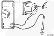
ActionMeasure the resistance from the fuel shutoff solenoid post to engine block ground. The fuel shutoff solenoid must be between 20°C [68°F] and 25°C [78°F] before using the resistance specifications listed. |
|
|
|
Is the fuel shutoff solenoid resistance:
|
||
| YES | NO | |
| No Repair |
Replace the fuel shutoff solenoid. Use the following procedure in the Troubleshooting and Repair Manual, CM870 Electronic Control System Signature™ and ISX Engines, Bulletin 4021334.Refer to Procedure 019-050 in Section 19. |
|
|
Repair complete
|
||
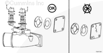
| Guided Step 3D – Check fuel shutoff valve actuator. | ||
|---|---|---|
Conditions
ActionCheck the valve disc, valve seat, and actuator disc for dirt, metal debris, bonding separation, corrosion, cracks, or wear. n/a |
|
|
|
Debris or damage found on the valve disc, valve seat, or actuator disc? |
||
| YES | NO | |
|
Replace the damaged fuel shutoff valve component. Use the following procedure in the Troubleshooting and Repair Manual, CM870 Electronic Control System Signature™ and ISX Engines, Bulletin 4021334. Refer to Procedure 019-050 in Section 19. |
No Repair | |
|
Repair complete
|
||
| Guided Step 3E – Check for correct priming pump operation, if equipped. | |
|---|---|
Conditions
ActionListen for lift pump operation after the keyswitch is turned to the ON position. Not all ISX engines use a priming pump and not all priming pumps actuate at keyswitch ON. Understand which system is present on this engine before beginning this step. |
|
|
Does the lift pump operate after turning the keyswitch ON? |
|
| YES | NO |
| No Repair |
Check or replace the lift pump. Use the following procedure in the Signature™, ISX, and QSX15 Service Manual, Bulletin 3666239. Refer to Procedure 005-045 in Section 5. |
|
Repair complete
|
|
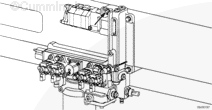
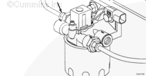
| Guided Step 3E-1 – Check priming pump pressure. | ||
|---|---|---|
Conditions
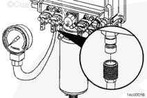
ActionMeasure the priming pressure at the quick connect fitting located on the top of the integrated fuel system module (IFSM). Use the following procedure in the Signature™, ISX, and QSX15 Service Manual, Bulletin 3666239. Refer to Procedure 005-045 in Section 5. |
|
|
|
Does pump pressure meet the 69 kPa [10 psi] specification? |
||
| YES | NO | |
| No Repair |
Replace the lift pump. Use the following procedure in the Signature™ ISX, and QSX15 Service Manual, Bulletin 3666239. Refer to Procedure 005-045 in Section 5. |
|
|
Repair complete
|
||
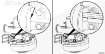
| Guided Step 3F – Check for coolant in the EGR transfer tube. | |
|---|---|
Conditions
ActionRemove the EGR transfer hose from the EGR cooler outlet. n/a |
|
|
Is coolant present in the crossover tube? |
|
| YES | NO |
|
See the Coolant Loss – Internal symptom tree. |
Perform the next troubleshooting procedure as outlined in Step 2 |
|
Repair complete
|
|
Guided Step 4 – Fuel system checks.
| Guided Step 4A – Verify the fuel system has been primed. | |
|---|---|
Conditions
ActionIf entering this tree after a component has been replaced in the fuel system, or after the engine has been run out of fuel, verify the fuel system has been properly primed before proceeding.
|
|
|
Has the fuel system been properly primed? |
|
| YES | NO |
| No Repair |
Prime the fuel system.
|
|
repair complete
|
|
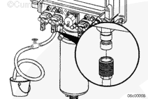
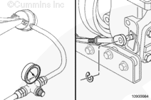
| Guided Step 4B – Check for air in the fuel. | ||
|---|---|---|
Conditions
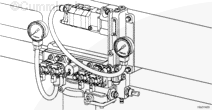
ActionConnect the equipment to the quick-connect fitting at the fuel module as shown.
|
|
|
|
Are air bubbles visible in the coil of clear tubing? |
||
| YES | NO | |
|
Locate and correct the cause of air ingestion in the OEM fuel supply system or damaged suction-side fuel filter sealing ring. With EGR: Check the ECM cooling plate, associated plumbing, and o-ring seals for failures that can cause air ingestion. Repair or replace the malfunctioning component. Use the following procedure in the Signature™, ISX, and QSX15 Service Manual, Bulletin 3666239. Refer to Procedure 006-020 in Section 6. |
No Repair | |
|
Repair complete
|
||
| Guided Step 4C – Check fuel inlet restriction. | ||
|---|---|---|
Conditions
ActionIf the engine uses a priming pump, wait until after the priming pump has turned off and observe the reading on the vacuum gauge. Check the fuel inlet restriction. Use the following procedure in the Signature™, ISX, and QSX15 Service Manual, Bulletin 3666239. Refer to Procedure 006-020 n Section 6. |
|
|
|
Is fuel inlet restriction less than the specifications listed below? Dirty – 305 mm-Hg [12 in-Hg]; New – 203 mm-Hg [8 in-Hg] |
||
| YES | NO | |
| No Repair |
Locate the cause of high fuel inlet restriction. Check the suction-side fuel filter and fuel supply lines. For QSX15 only, check the 300 micron inlet filter screen for debris. Use the following procedure in the Signature™, ISX, and QSX15 Service Manual, Bulletin 3666239. Refer to Procedure 005-073 in Section 5. |
|
|
Repair complete
|
||
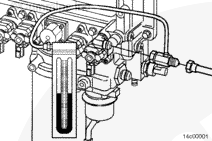
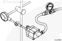
| Guided Step 4D – Check drain line restriction. | ||
|---|---|---|
Conditions
ActionObserve reading on the pressure gauge. n/a |
|
|
|
Is fuel drain line restriction less than 229 mm-Hg [9 in-Hg]? |
||
| YES | NO | |
| No Repair |
Locate cause of high fuel drain line restriction in OEM fuel return line. |
|
|
Repair complete
|
||
| Guided Step 4E – Check rail fuel pressure. | ||
|---|---|---|
Conditions
ActionRead the rail fuel pressure at low idle and high idle. Read the rail fuel pressure while cranking if the engine will not start.
With EGR
|
|
|
|
Does the rail fuel pressure meet the specification? |
||
| YES | NO | |
| No Repair |
When cranking, make sure the fuel system is primed for at least 30 seconds. |
|
|
Perform the next troubleshooting procedure as outlined in Step 2
|
With EGR 4E-1
|
|
| Guided Step 4E-1 – Check the pressure side fuel filter restriction. | ||
|---|---|---|
Conditions
ActionRead the fuel pressure drop across the pressure side fuel filter at high idle or while cranking if the engine will not start. n/a |
|
|
|
Is the pressure side fuel filter pressure drop less than 517 kPa [75 psi]? |
||
| YES | NO | |
| No Repair |
Replace the pressure side fuel filter. Use the following procedure in the Signature™, ISX, and QSX15 Service Manual, Bulletin 3666239. Refer to Procedure 006-015 in Section 6. |
|
|
Repair complete
|
||
| Guided Step 4E-2 – Check 1724 kPa [250 psi] pressure regulator. | ||
|---|---|---|
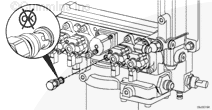
ConditionsTurn keyswitch OFF. ActionRemove the 1724-kPa [250-psi] fuel pressure regulator.
|
|
|
|
Is the 1724 kPa [250 psi] pressure regulator free of debris or damage? |
||
| YES | NO | |
| No Repair |
Replace 1724 kPa [250 psi] regulator. Use the following procedure in the Signature™, ISX, and QSX15 Service Manual, Bulletin 3666239. Refer to Procedure 005-073 in Section 5. |
|
|
Repair complete
|
||
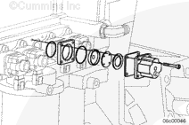
| Guided Step 4E-3 – Check 2206 kPa [320 psi] or 2620 kPa [380 psi] pressure regulator. | ||
|---|---|---|
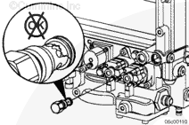
ConditionsTurn keyswitch OFF. ActionRemove the 2206 kPa [320 psi] fuel pressure regulator. Inspect for debris, damage, or incomplete sealing of the regulator. With EGR Remove the 2620 kPa [380 psi] fuel pressure regulator. Inspect for debris, damage, or incomplete sealing of the regulator. |
|
|
|
Is the pressure regulator free of debris or damage? |
||
| YES | NO | |
|
Replace the fuel pump. Use the following procedure in the Signature™, ISX, and QSX15 Service Manual, Bulletin 3666239. Refer to Procedure 005-016 in Section 5. |
Replace the 2206 kPa [320 psi] regulator. With EGR Replace the 2620 kPa [380 psi] regulator. Use the following procedure in the Signature™, ISX, and QSX15 Service Manual, Bulletin 3666239. Refer to Procedure 005-073 in Section 5. |
|
|
Repair complete
|
Repair complete
|
|
Guided Step 5 – Injector and Actuator Diagnostics.
| Guided Step 5A – Perform the injector check valve leak test. | |
|---|---|
Conditions
ActionPerform the injector check valve leak test to check for internal injector check valve damage. Use the following procedure in the Signature™, ISX, and QSX15 Service Manual, Bulletin 3666239. Refer to Procedure 006-026 in Section 6. INSITE™ electronic service tool Injector Check Valve Diagnostics Test can be used as an initial test before performing the mechanical check outlined in Procedure 006-026 in Section 6. If INSITE™ electronic service tool does not detect a failed injector, perform the injector leak test. Use the following procedure in the Signature™, ISX, and QSX15 Service Manual, Bulletin 3666239. Refer to Procedure 006-026 in Section 6. |
|
|
Did the injector leak test detect a leaking injector? |
|
| YES | NO |
|
Replace the leaking injector. Use the following procedure in the Signature™, ISX, and QSX15 Service Manual, Bulletin 3666239. Refer to Procedure 006-026 in Section 6. |
No Repair |
|
Repair complete
|
|
| Guided Step 5B – Perform INSITE™ electronic service tool Cylinder Performance Test. | |
|---|---|
Conditions
ActionPerform INSITE™ electronic service tool Cylinder Performance Test. ISX Signature™:
ISX CM870:
|
|
|
Does performing INSITE™ electronic service tool Cylinder Performance Test identify a single malfunctioning injector? |
|
| YES | NO |
| No Repair | No Repair |
| Guided Step 5B-1 – Perform INSITE™ electronic service tool Cylinder Performance Test at 600 rpm. | |
|---|---|
Conditions
ActionSkip this step and move on to step 5B-2 if the rpm value is the same as that used in step 5B. Adjust the low speed to 600 rpm and perform the INSITE™ electronic service tool Cylinder Performance Test. ISX Signature™:
ISX CM870:
|
|
|
Does performing INSITE™ electronic service tool Cylinder Performance Test identify a single malfunctioning injector? |
|
| YES | NO |
| No Repair | No Repair |
| Guided Step 5B-2 – Perform INSITE™ electronic service tool Cylinder Performance Test at 700 rpm. | |
|---|---|
Conditions
The idle speed may need to be adjusted to perform this test. Toggle the cruise control increment/decrement switch to see if the idle speed can be adjusted. If not, use INSITE™ electronic service tool to either enable the Adjustable Low Idle Speed feature or adjust the Low Idle Speed. ActionSkip this step and move on to step 5B-3 if the RPM value is the same as that used in step 5B. Adjust the low speed to 700 rpm and perform the INSITE™ electronic service tool Cylinder Performance Test. ISX Signature™:
ISX CM870:
|
|
|
Does performing INSITE™ electronic service tool Cylinder Performance Test identify a single malfunctioning injector? |
|
| YES | NO |
| No Repair | No Repair |
| Guided Step 5B-3 – Perform INSITE™ electronic service tool Cylinder Performance Test at 800 rpm. | |
|---|---|
Conditions
The idle speed may need to be adjusted to perform this test. Toggle the cruise control increment/decrement switch to see if the idle speed can be adjusted. If not, use INSITE™ electronic service tool to either enable the “Adjustable Low Idle Speed” feature or adjust the Low Idle Speed. ActionSkip this step and move on to step 5C if the rpm value is the same as that used in step 5B. Adjust the low speed to 800 rpm and perform the INSITE™ electronic service tool Cylinder Performance Test. ISX Signature™:
ISX CM870:
|
|
|
Does performing INSITE™ electronic service tool Cylinder Performance Test identify a single malfunctioning injector? |
|
| YES | NO |
| No Repair | No Repair |
| Guided Step 5C – Perform INSITE™ electronic service tool Cylinder Cutout Test | |
|---|---|
Conditions
ActionPerform INSITE™ electronic service tool cylinder cutout test. A failing cylinder will have no effect on engine sound and operation when cut out using this test. |
|
|
Do all cylinders pass the cylinder cutout test? |
|
| YES | NO |
| No Repair | No Repair |
| Guided Step 5C-1 – Perform INSITE™ electronic service tool cylinder cutout test on individual injector banks. | |
|---|---|
Conditions
ActionPerform the INSITE™ electronic service tool cylinder cutout test.
|
|
|
Can a malfunctioning bank of injectors be isolated by operating the engine on either bank of injectors? |
|
| YES | NO |
| No Repair | No Repair |
| Guided Step 5C-2 – Perform INSITE™ electronic service tool Cylinder Cutout Test single cylinder operation. | |
|---|---|
Conditions
ActionPerform the INSITE™ electronic service tool cylinder cutout test. Operate the engine on the cylinder identified by the Cylinder Performance Test by disabling 5 cylinders with INSITE™ electronic service tool and only operating on the suspect cylinder. To disable 5 cylinders with INSITE™ electronic service tool, click on the cylinder numbers until only 1 cylinder is enabled. The engine should roughly maintain idle speed when operating on a single cylinder. A weak or misfiring cylinder will be detected if the engine dies or can not maintain idle speed when operating on a single cylinder. Continue testing all 6 cylinders by operating the engine on each individual injector. If the engine will not run on 1 cylinder regardless of the cylinder selected, increase the idle RPM and retest. Do not run the engine on 1 cylinder for an extended period of time. |
|
|
Can a malfunctioning injector be isolated by operating the engine on a single injector? |
|
| YES | NO |
| No Repair | No Repair |
| Guided Step 5C-3 – Verify overhead adjustments are correct for the suspected malfunctioning injector. | |
|---|---|
Conditions
ActionMeasure the overhead settings for the suspected malfunctioning injector.
|
|
|
Are the overhead settings within the reset limits outlined in Procedure 003-004 in Section 3? |
|
| YES | NO |
|
Replace the malfunctioning injector. Use the following procedure in the Signature™, ISX, and QSX15 Service Manual, Bulletin 3666239. Refer to Procedure 006-026 in Section 6. |
Adjust the overhead settings. Use the following procedure in the Signature™, ISX, and QSX15 Service Manual, Bulletin 3666239. Refer to Procedure 003-004 in Section 3. Perform the Cylinder Performance Test to determine if a misfire still exists after adjusting the overhead settings. |
|
Repair complete
|
|
| Guided Step 5D – Swap the front and rear metering actuators. | |
|---|---|
Conditions
ActionSwap the front and rear metering actuator to determine if the failed bank of cylinders follows a specific metering actuator.
|
|
|
Did the cylinder performance test find a malfunctioning bank? |
|
| YES | NO |
|
Replace the malfunctioning metering actuator. Use the following procedure in the Troubleshooting and Repair Manual, CM870 Electronic Control System Signature™ and ISX Engines, Bulletin 4021334. |
No Repair |
|
Repair complete
|
|
| Guided Step 5E – Swap the front and rear timing actuators. | |
|---|---|
Conditions
ActionSwap the front and rear timing actuator to determine if the failed bank of cylinders follows a specific timing actuator.
|
|
|
Does the malfunctioning bank follow the timing actuator? |
|
| YES | NO |
|
Replace the timing actuator. Use the following procedure in the Troubleshooting and Repair Manual, CM870 Electronic Control System Signature™ and ISX Engines, Bulletin 4021334. Refer to Procedure 019-111 in Section 19. |
No Repair |
|
Repair Complete
|
Perform the next troubleshooting procedure as outlined in Step 2
|
Guided Step 6 – Air handling diagnostic checks.
| Guided Step 6A – Start the engine and read the fault codes. | |
|---|---|
Conditions
ActionCheck the fault codes with the engine running.
|
|
|
Active fault codes? |
|
| YES | NO |
| No Repair | No Repair |
|
Go to appropriate fault code troubleshooting tree
|
|
| Guided Step 6B – Check the air intake system for leaks. | |
|---|---|
Conditionsn/a ActionCheck the air intake system for leaks. Use the following procedure in the Signature™, ISX, and QSX15 Service Manual, Bulletin 3666239. Refer to Procedure 010-024 in Section 10. On engines equipped with a turbocharged air compressor, one often overlooked item as a source of air leaks is the air compressor intake line. The intake line supplies intake air from the intake of the engine to the air compressor. |
|
|
Leaks found? |
|
| YES | NO |
|
Replace the damaged component. |
No Repair |
|
Repair complete
|
|
| Guided Step 6C – Check air intake restriction. | |
|---|---|
Conditions
ActionCheck the intake system restriction by installing a vacuum gauge or water manometer into the air intake system. Use the following procedure in the Signature™, ISX, and QSX15 Service Manual, Bulletin 3666239. Refer to Procedure 010-031 in Section 10. |
|
|
Restriction greater than 635 mm-H2O [25 in-H2O] for a used air filter or 254 mm-H2O [10 in-H2O] for a new filter? |
|
| YES | NO |
|
Correct the cause of high intake air restriction. Check for plugged air filter or restricted air intake piping. |
No Repair |
|
Repair complete
|
|
| Guided Step 6D – Inspect the charge-air cooler. | |
|---|---|
Conditions
ActionInspect the charge-air cooler for cleanliness, cracks, holes, or other damage.
The pressure test can be used to verify charge-air cooler problems. |
|
|
Problems found with the charge-air cooler? |
|
| YES | NO |
|
Repair or replace the charger-air cooler. Refer to the OEM service manual. |
No Repair |
|
Repair complete
|
|
| Guided Step 6E – Check the exhaust restriction. | |
|---|---|
Conditions
ActionCheck exhaust restriction by installing a pressure gauge into the exhaust system just past the turbocharger outlet. Use the following procedure in the Signature™, ISX, and QSX15 Service Manual, Bulletin 3666239. Refer to Procedure 011-009 in Section 11. |
|
|
Restriction between 518 mm-H2O [20.4 in-H2O] or 38 mm-Hg [1.5 in-Hg] and 1036 mm-H2O [40.8 in-H2O] or 76 mm-Hg [3.0 in-Hg]? |
|
| YES | NO |
| No Repair |
Repair the exhaust system for the source of the high restriction. |
|
Repair complete
|
|
| Guided Step 6F – Inspect the turbocharger blades for damage. | |
|---|---|
Conditions
ActionInspect the compressor and turbine blades for damage or wear. n/a |
|
|
Damage found on turbocharger blades? |
|
| YES | NO |
|
Replace the turbocharger. Use the following procedure in the Signature™, ISX, and QSX15 Service Manual, Bulletin 3666239. Refer to Procedure 010-033 in Section 10. |
No Repair |
|
Repair complete
|
|
| Guided Step 6G – Determination of turbocharger type. | |
|---|---|
Conditionsn/a ActionDetermine if the turbocharger is a wastegated or variable geometry turbocharger. n/a |
|
|
Is the turbocharger a variable geometry turbocharger? |
|
| YES | NO |
| No Repair | No Repair |
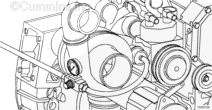
| Guided Step 6H – Check the variable geometry actuator rod for correct travel. | ||
|---|---|---|
Conditions
ActionUse INSITE™ electronic service tool to start the Turbocharger Actuator Test.
The turbocharger actuator will move quickly and crisply. If the actuator rod movement is slow, there could be a problem with the air supply, a faulty ground connection on the engine or chassis, or mechanical problems with the variable geometry turbocharger assembly. |
|
|
|
Does the turbocharger actuator rod extend between 10 and 12 mm [0.394 and 0.472 in]? |
||
| YES | NO | |
| No Repair | No Repair | |
| Guided Step 6H-1 – Check for air leaks and inspect air lines. | |
|---|---|
Conditions
ActionUse INSITE™ electronic service tool to perform the Turbocharger Actuator Test. Select the Extend Actuator position. Listen for air leaks at the following components:
A small amount of air could possibly be heard escaping from the turbocharger control valve during the turbocharger actuator test. This is a normal condition for the valve to achieve output regulation pressure. Do not replace the turbocharger control valve for this condition. |
|
|
Air leaks found in the system? |
|
| YES | NO |
|
Repair air leaks. |
No Repair |
|
Repair complete
|
|
| Guided Step 6H-2 – Check the engine and vehicle grounds. | ||
|---|---|---|
Conditions
ActionCheck for a loose or corroded engine, chassis, or battery ground connection.
|
|
|
|
Connections tight and corrosion-free? |
||
| YES | NO | |
| No Repair |
Tighten the connections.
|
|
|
Repair complete
|
||
| Guided Step 6H-3 – Check for air pressure at the turbocharger control valve outlet. | |
|---|---|
Conditions
ActionUse INSITE™ electronic service tool to perform the Turbocharger Actutator Test. Select the Retract Actuator position. Remove the air line connection at the outlet of the turbocharger control valve. Install an M12 Compuchek™ fitting at the outlet of the turbocharger control valve. Install an air pressure gauge that is capable of reading at least 1034 kPa [150 psi]. Use INSITE™ electronic service tool to perform the Turbocharger Actuator Test. Select the Extend Actuator position. |
|
|
Is vehicle air tank pressure present at the turbocharger control valve outlet? |
|
| YES | NO |
| No Repair | No Repair |
| Guided Step 6H-4 – Check for air pressure at the turbocharger control valve outlet. | |
|---|---|
Conditions
ActionUse INSITE™ electronic service tool to perform the Turbocharger Actuator Test. Select the Retract Actuator position.
|
|
|
Does the pressure gauge read more than 103 kPa [15 psi] after 5 minutes? |
|
| YES | NO |
|
Replace the turbocharger control valve. Use the following procedure in the Troubleshooting and Repair Manual, CM870 Electronic Control System Signature™ and ISX Engines, Bulletin 4021334 or reference the OEM service manual. Refer to Procedure 019-388 in Section 19. |
No Repair |
|
Repair complete
|
|
| Guided Step 6H-5 – Check for correct turbocharger actuator travel. | ||
|---|---|---|
Conditions
ActionDamage to the turbocharger can result if the proper removal procedure is not followed. Remove the variable geometry actuator from the turbocharger. Use the following procedure in the Signature™, ISX, and QSX15 Service Manual, Bulletin 3666239. Refer to Procedure 010-113 in Section 10. Use INSITE™ electronic service tool to perform the Turbocharger Actuator Test.
|
|
|
|
Does the turbocharger actuator rod travel at least 12 mm [0.472 in]? |
||
| YES | NO | |
|
Replace the turbocharger assembly. Use the following procedure in the Signature™, ISX, and QSX15 Service Manual, Bulletin 3666239. Refer to Procedure 010-033 in Section 10. |
Replace the turbocharger actuator. Use the following procedure in the Signature™, ISX, and QSX15 Service Manual, Bulletin 3666239. Refer to Procedure 010-113 in Section 10. |
|
|
Repair complete
|
Repair complete
|
|
| Guided Step 6H-6 – Check for air pressure at the turbocharger control shutoff valve outlet. | ||
|---|---|---|
Conditions
ActionUse INSITE™ electronic service tool to perform the Turbocharger Actuator Test.
|
|
|
|
Can air be heard escaping from the turbocharger control shutoff valve outlet? |
||
| YES | NO | |
|
Replace the turbocharger control valve. Use the following procedure in the Troubleshooting and Repair Manual, CM870 Electronic Control System Signature™ and ISX Engines, Bulletin 4021334 or reference the OEM service manual. Refer to Procedure 019-388 in Section 19. |
No Repair | |
|
Repair complete
|
||
| Guided Step 6H-7 – Check for air pressure at the turbocharger control shutoff valve inlet. | |
|---|---|
Conditions
ActionVerify the OEM air supply line is connected to the correct port on the turbocharger control shutoff valve.
|
|
|
Can air be heard escaping from the turbocharger control shutoff valve inlet? |
|
| YES | NO |
| No Repair |
Repair the air supply from the OEM air tanks. |
|
Repair complete
|
|
| Guided Step 6H-8 – Check for plugged turbocharger control shutoff valve filter. | |
|---|---|
Conditions
ActionUse INSITE™ electronic service tool to perform the Turbocharger Actuator Test.
|
|
|
Is an air leak present at the turbocharger control shutoff valve filter head? |
|
| YES | NO |
|
Replace the turbocharger control shutoff valve filter. Use the following procedure in the Signature™, ISX, and QSX15 Service Manual, Bulletin 3666239. Refer to Procedure 010-114 in Section 10. |
Replace the turbocharger control shutoff valve. Use the following procedure in the Troubleshooting and Repair Manual, CM870 Electronic Control System Signature™ and ISX Engines, Bulletin 4021334 or reference the OEM service manual. Refer to Procedure 019-386 in Section 19. |
|
Repair complete
|
Repair complete
|
| Guided Step 6I – Perform INSITE™ Electronic Service Tool EGR Valve/Turbocharger Operational Test. | |
|---|---|
Conditions
ActionUse INSITE™ electronic service tool to select the EGR/VGT Operational Test . Prior to operating INSITE™ electronic service tool EGR Valve and EGR Valve/Turbocharger Operational Test, the ECM Calibration Software Phase can possibly need to be updated to the latest Software Phase. The ECM Calibration Phase Software can be checked in INSITE™ electronic service tool, under ‘Features and Parameters’. Expand the selection for ‘System ID and Dataplate’ and go to ‘Calibration Information’. If the Software Phase is earlier than shown below, calibrate the ECM, use the January 2006 INCAL™ CD-ROM, or later. Engines with the Software Phase listed below or later do not require a calibration. ISX engines with CM870 (engines built after January 2004) require Software Phase 06050302. ISX engines with CM870 (engines built before January 2004) require no changes at this time. This is a warrantable calibration change.
|
|
|
Does the Turbocharger Operational Test pass? |
|
| YES | NO |
| No Repair | No Repair |
|
Perform the next troubleshooting procedure as outlined in Step 2
|
|
| Guided Step 6I-1 – Check the engine and vehicle grounds. | ||
|---|---|---|
Conditions
ActionCheck for a loose or corroded engine, chassis, or battery ground connection.
|
|
|
|
Connections tight and corrosion-free? |
||
| YES | NO | |
|
Replace the variable geometry turbocharger. Use the following procedure in the Signature™, ISX, and QSX15 Service Manual, Bulletin 3666239. Refer to Procedure 010-033 in Section 10. |
Tighten the connections.
|
|
|
Repair complete
|
Repair complete
|
|
| Guided Step 6J – Inspect the wastegate actuator hose. | ||
|---|---|---|
Conditions
ActionInspect the integral wastegate actuator hose for cracks or holes. n/a |
|
|
|
Holes or cracks found in the wastegate actuator hose? |
||
| YES | NO | |
|
Replace wastegate actuator hose. |
No Repair | |
|
Repair complete
|
||
| Guided Step 6K – Inspect the wastegate actuator rod for travel. | ||
|---|---|---|
Conditions
ActionApply a regulated air supply of 310 kPa [45 psi] to the actuator and check for actuator movement. n/a |
|
|
|
Does the wastegate actuator rod move? |
||
| YES | NO | |
| No Repair | No Repair | |
| Guided Step 6K-1 – Inspect wastegate actuator rod for travel. | ||
|---|---|---|
Conditions
ActionApply a regulated air supply of 310 kPa [45 psi] to the actuator and check for actuator movement. n/a |
|
|
|
Does the wastegate actuator rod move? |
||
| YES | NO | |
|
Move the wastegate lever on the turbocharger back and forth and check for smooth operation. Replace turbocharger assembly if the wastegate is seized. Use the following procedure in the Signature™, ISX, and QSX15 Service Manual, Bulletin 3666239. Refer to Procedure 010-033 in Section 10. |
Replace the wastegate actuator. Use the following procedure in the Signature™, ISX, and QSX15 Service Manual, Bulletin 3666239. Refer to Procedure 010-050 in Section 10. |
|
|
Repair complete
|
Repair complete
|
|
| Guided Step 6L – Measure resistance of the four-stage wastegate controllers, if equipped. | |
|---|---|
Conditions
ActionMeasure the resistance from the wastegate controller post to engine block ground. The wastegate controller solenoids must be between 20°C and 26°C [68°F and 79°F] before using the resistance specifications listed. |
|
|
Are the wastegate controller solenoid resistances between 7.0 and 8.0 ohms? |
|
| YES | NO |
| No Repair |
Replace the damaged wastegate controller. Use the following procedure in the Signature™, ISX, and QSX15 Service Manual, Bulletin 3666239. Refer to Procedure 010-109 in Section 10. |
|
Repair complete
|
|
| Guided Step 6M – Inspect four-stage wastegate controller, if equipped. | ||
|---|---|---|
Conditions
ActionCheck the valve disc, valve seat, and actuator disc for dirt, metal debris, bonding separation, corrosion, cracks, or wear. n/a |
|
|
|
Damage or debris found on the valve disc, valve seat, or actuator disc? |
||
| YES | NO | |
|
Replace or clean damaged components. |
No Repair | |
|
Repair complete
|
Perform the next troubleshooting procedure as outlined in Step 2
|
|
;)
;)
;)
;)
;)
;)
;)
;)
;)
;)
;)
;)
;)
;)
;)
;)
;)
;)
;)
;)
;)
;)
;)
;)
;)
;)
;)
;)
;)
;)
;)
;)
;)
;)
;)
;)
;)
;)
;)
;)
;)
;)
Guided Step 7 – Check EGR valve for proper operation.
| Guided Step 7A – Check for air leaks in the EGR system. | |
|---|---|
Conditionsn/a ActionCheck for leaks in the EGR connection tubing and connections. Soot streaks can be noticeable where leaks are present. |
|
|
Air leaks found in the EGR connection tubing? |
|
| YES | NO |
|
Repair any leaks in the EGR system. |
No Repair |
|
Repair complete
|
|
| Guided Step 7B – Check repair history. | |
|---|---|
Conditionsn/a ActionCheck with the customer for a recent EGR valve replacement. n/a |
|
|
Is there any record of the poppet head missing? |
|
| YES | NO |
|
Remove the exhaust manifold and run a wire through every port to check for the missing poppet head. |
No Repair |
| Guided Step 7C – Perform EGR Valve Test. | |
|---|---|
Conditions
ActionPerform INSITE™ electronic service tool EGR Valve Test. Prior to operating INSITE™ electronic service tool EGR Valve and EGR Valve/Turbocharger Operational Test, the ECM Calibration Software Phase can possibly need to be updated to the latest Software Phase. The ECM Calibration Phase Software can be checked in INSITE™ electronic service tool, under ‘Features and Parameters’. Expand the selection for ‘System ID and Dataplate’ and go to ‘Calibration Information’. If the Software Phase is earlier than shown below, calibrate the ECM, use the January 2006 INCAL™ CD-ROM, or later. Engines with the Software Phase listed below or later do not require a calibration. ISX engines with CM870 (engines built after January 2004) require Software Phase 06050302. ISX engines with CM870 (engines built before January 2004) require no changes at this time. This is a warrantable calibration change.
|
|
|
Does the EGR Valve Test pass? |
|
| YES | NO |
| No Repair |
Replace the EGR valve. Use the following procedure in the Signature™, ISX, and QSX15 Service Manual, Bulletin 3666239. Refer to Procedure 011-022 in Section 11. |
|
Perform the next troubleshooting procedure as outlined in Step 2
|
Repair complete
|
Guided Step 8 – Verify electronic features are operating correctly.
| Guided Step 8A – Verify accelerator pedal travel. | |
|---|---|
Conditions
ActionUse INSITE™ electronic service tool to monitor Accelerator Pedal while fully depressing and releasing the accelerator pedal. n/a |
|
|
Does the Accelerator Pedal read 0 percent when the accelerator is released and 100 percent when the accelerator is depressed? |
|
| YES | NO |
| No Repair |
Determine and correct the cause of accelerator pedal restriction. |
|
Repair complete
|
|
| Guided Step 8B – Monitor vehicle speed. | |
|---|---|
Conditions
ActionUse INSITE™ electronic service tool to monitor Vehicle Speed while the vehicle is not moving. n/a |
|
|
Does the vehicle speed read 0 when the vehicle is not moving? |
|
| YES | NO |
| No Repair |
Check the vehicle speed sensor and circuit or locate the cause of the vehicle speed interference. |
|
Repair complete
|
|
| Guided Step 8C – Verify electronic feature settings are correct. | |
|---|---|
Conditions
ActionUse INSITE™ electronic service tool to verify the following adjustable parameters are correctly set:
|
|
|
Are the electronic features set correctly? |
|
| YES | NO |
| No Repair |
Correct programmable features. |
|
Step 8D
|
Repair complete
|
| Guided Step 8D – Check the barometric pressure sensor reading. | |
|---|---|
Conditions
ActionCheck for correct barometric pressure sensor reading.
|
|
|
Is the barometric pressure sensor reading in INSITE™ electronic service tool within 5 percent of the present local barometric pressure reading? |
|
| YES | NO |
| No Repair |
Replace the barometric pressure sensor. Use the following procedure in the Troubleshooting and Repair Manual, CM870 Electronic Control System Signature™ and ISX Engines, Bulletin 4021334 or reference the OEM service manual. Refer to Procedure 019-004 in Section 19. |
|
Perform the next troubleshooting procedure as outlined in Step 2
|
Repair complete
|
Guided Step 9 – Perform base engine mechanical checks.
| Guided Step 9A – Verify overhead adjustments are correct. | |
|---|---|
Conditions
ActionMeasure the overhead settings. Valve Lash Reuse Limits:
|
|
|
Overhead settings within the reuse limits? |
|
| YES | NO |
| No Repair |
Adjust the overhead settings. Use the following procedure in the Signature™, ISX, and QSX15 Service Manual, Bulletin 3666239. Refer to Procedure 003-004 in Section 3. |
|
Repair complete
|
|
| Guided Step 9B – Verify engine brake adjustment. | |
|---|---|
Conditions
ActionVerify the engine brakes are operating correctly.
|
|
|
Engine brake settings within the reuse limits? |
|
| YES | NO |
| No Repair |
Adjust the engine brake settings. Use the following procedure in the Signature™, ISX, and QSX15 Service Manual, Bulletin 3666239. Refer to Procedure 020-004 in Section 20. |
|
Repair complete
|
|
| Guided Step 9C – Measure turbocharger axial and radial clearance. | |
|---|---|
Conditions
ActionMeasure the axial and radial clearance of the turbocharger. Use the following procedure in the Signature™, ISX, and QSX15 Service Manual, Bulletin 3666239. Refer to Procedure 010-033 in Section 10. |
|
|
Axial and radial clearances within specification? |
|
| YES | NO |
| No Repair |
Replace the turbocharger assembly. Use the following procedure in the Signature™, ISX, and QSX15 Service Manual, Bulletin 3666239. Refer to Procedure 010-033 in Section 10. |
|
Repair complete
|
|
| Guided Step 9D – Verify engine blowby is within specification. | |
|---|---|
Conditions
ActionLoad engine to rated rpm on a chassis dynamometer. Measure the engine blowby. Use the following procedure in the Signature™, ISX, and QSX15 Service Manual, Bulletin 3666239. Refer to Procedure 014-010 in Section 14. |
|
|
Engine blowby measurements within specification? |
|
| YES | NO |
| No Repair |
Engine may need to be rebuilt. See engine rebuild specifications. |
|
Repair complete
|
|
| Guided Step 9E – Verify injection timing is correct. | |
|---|---|
Conditions
ActionVerify the injection timing is correct. Measure the injection timing. Use the following procedure in the Signature™, ISX, and QSX15 Service Manual, Bulletin 3666239. Refer to Procedure 006-025 in Section 6. If the injection timing is found to be out of specification, bar the engine to “insert pin” and install the crankshaft pin. Install the appropriate injector camshaft wedge to set the correct injection timing. Use the following procedure in the Signature™, ISX, and QSX15 Service Manual, Bulletin 3666239. Refer to Procedure 001-088 in Section 1. |
|
|
Injection timing within specification? |
|
| YES | NO |
| No Repair |
Correct the injection timing. Use the following procedure in the Signature™, ISX, and QSX15 Service Manual, Bulletin 3666239. Refer to Procedure 001-088 in Section 1. |
|
Repair complete
|
|
| Guided Step 9F – Check for a damaged vibration damper. | |
|---|---|
Conditions
ActionRemove and visually inspect the vibration damper.
|
|
|
Vibration damper damaged or out of specification? |
|
| YES | NO |
|
Replace the vibration damper. Use the following procedure in the Signature™, ISX, and QSX15 Service Manual, Bulletin 3666239. Refer to Procedure 001-052 in Section 1. |
No Repair |
|
Repair complete
|
Perform the next troubleshooting procedure as outlined in Step 2
|
Guided Step 10 – Check the EGR differential pressure sensor and exhaust gas pressure sensor tubes.
| Guided Step 10A – Check the EGR differential pressure tubes for cracks, restrictions, or leaks. | |
|---|---|
Conditions
ActionInspect the EGR differential pressure tubes for cracks, restrictions, or leaks. Soot streaks can indicate that the line is loose or cracked. |
|
|
Cracks, restrictions, or leaks present? |
|
| YES | NO |
|
Tighten or replace the EGR differential pressure tubes. Use the following procedure in the Signature™, ISX, and QSX15 Service Manual, Bulletin 3666239. Refer to Procedure 011-026 in Section 11. |
No Repair |
|
Repair complete
|
|
| Guided Step 10B – Check the exhaust gas pressure tubes for cracks, restrictions, or leaks. | |
|---|---|
Conditions
ActionInspect the exhaust gas pressure tubes for cracks, restrictions, or leaks. Soot streaks can indicate that the line is loose or cracked. |
|
|
Cracks, restrictions, or leaks present? |
|
| YES | NO |
|
Tighten or replace the exhaust gas pressure tubes. Use the following procedure in the Signature™, ISX, and QSX15 Service Manual, Bulletin 3666239. Refer to Procedure 011-027 in Section 11. |
No Repair |
|
Repair complete
|
Perform the next troubleshooting procedure as outlined in Step 2
|