 |
Fuel Economy Troubleshooting Tree

Symptoms
- Fuel Consumption Excessive.
How To Use This Tree
This symptom tree is to be used to troubleshoot fuel economy complaints. This tree is used along with the Fuel Consumption – Customer Complaint Form and the Driveability Low Power/Excessive Fuel – Consumption Checklist to help isolate engine, chassis, or driver issues associated with excessive fuel consumption.
Shop Talk
The Fuel Consumption – General Information section of the Troubleshooting and Repair Manual, Signature, ISX, QSX15 Engines, Bulletin 3666239 and Troubleshooting Excessive Fuel Consumption, Bulletin 3666094, should be referenced prior to any troubleshooting being performed on a customer’s engine.
NOTE: Prior to running the INSITE™ electronic service tool EGR Valve and EGR Valve/Turbocharger Operational Test, the ECM Calibration Software Phase could possibly need to be updated to the latest Software Phase. The ECM Calibration Phase Software can be checked in INSITE™ electronic service tool, under ‘Features and Parameters’. Expand the selection for ‘System ID and Dataplate’ and go to ‘Calibration Information’. If the Software Phase is earlier than shown below, recalibrate the ECM using the January 2006 INCAL™ CD-ROM, or later. Engines with the Software Phase listed below or later do not require a recalibration.
ISX engines with CM870 (engines built after January 2004) require Software Phase 06050302.
ISX engines with CM870 (engines built before January 2004) require no changes at this time.
This is a warrantable calibration change.
The cause of excessive fuel consumption is difficult to diagnose and correct because of the potential number of factors involved. Actual fuel consumption problems can be caused by any of the following factors:
- Engine factors
- Vehicle factors and specifications
- Environmental factors
- Driver technique and operating practices
- Fuel system factors
- Low power or driveability problems.
Before troubleshooting, it is important to determine the exact complaint. Is the complaint based on whether the problem is real or perceived, or does not meet driver expectations? The Fuel Consumption – Customer Complaint Form is a valuable list of questions that can be used to assist the service technician in determining the cause of the problem. Complete the form before troubleshooting the complaint. The following are some of the factors that must be considered when troubleshooting fuel consumption complaints.
- Excessive Idling Time: Idling the engine can use from 0.5 to 1.5 gallons per hour depending on the engine idle speed.
- Vehicle Aerodynamics: The largest single power requirement for a truck is the power needed to overcome air resistance. As a general rule, each 10 percent reduction in air resistance results in a 5 percent increase in mile per gallon.
- Rolling Resistance: Rolling resistance is the second largest consumer of power on a truck. The type of tire and tread design have a sizeable effect on fuel economy and performance. Changing from a bias ply to a low profile radial tire can reduce rolling resistance by about 36 percent.
- Environmental and Seasonal Weather Changes: As a general rule, there can be as much as 1 to 1.5 mile per gallon difference in fuel consumption, depending on the season and the weather conditions.
- Truck Route and Terrain: East and west routes experience almost continual crosswinds and head winds. Less fuel can be used on north and south routes where parts of the trip are not only warmer, but see less wind resistance.
- Driver Technique and Operating Practices: As a general rule, a 1 mile per hour increase in road speed equals a 0.1 mile per gallon increase in fuel consumption. This means that increasing road speed from 50 to 60 mph will result in a loss of fuel mileage of 1 mpg.
- Result of a low power or driveability problem: An operator will change driving style to compensate for a low power or driveability problem. Some things the driver is likely to do are (a) shift to a higher engine rpm or (b) run on the droop curve in a lower gear instead of upshifting to drive at part-throttle conditions. These changes in driving style will increase the amount of fuel used.
Additional vehicle factors, vehicle specifications, and axle alignment can also affect fuel consumption. For additional information on troubleshooting fuel consumption complaints, refer to Troubleshooting Excessive Fuel Consumption, Bulletin 3387245.
Troubleshooting Steps
| STEPS | SPECIFICATIONS | |
|---|---|---|
| STEP 1. | Verify the complaint. | |
| STEP 1A. Fill out the Fuel Consumption – Customer Complaint Form. | ||
| STEP 1B. Run VE/VMS™. | ||
| STEP 2. | Electronic checks using INSITE™ electronic service tool. | |
| STEP 2A. Check for fault codes. | ||
| STEP 2B. Confirm Features and Parameters. | ||
| STEP 2C. Check the ECM calibration. | ||
| STEP 2D. Monitor vehicle speed. | ||
| STEP 2D-1. Inspect the engine and chassis grounds. | ||
| STEP 3. | Fuel system inspection. | |
| STEP 3A. Inspect the vehicle for fuel leaks. | ||
| STEP 3B. Check the fuel inlet restriction. | ||
| STEP 3C. Check the drain line restriction. | ||
| STEP 3D. Check the fuel grade. | ||
| STEP 3E. Perform the INSITE™ electronic service tool Cylinder Performance Test. | ||
| STEP 3E-1. Interpret the results of the Cylinder Performance Test. | ||
| STEP 3E-2. Interpret the results of the Cylinder Performance Test. | ||
| STEP 3E-3. Measure the resistance between the actuator and the actuator base. | ||
| STEP 3E-4. Swap the front and rear fueling actuators. | ||
| STEP 3E-5. Swap the front and rear timing actuators. | ||
| STEP 4. | Check the air handling system. | |
| STEP 4A. Check the air intake restriction. | ||
| STEP 4B. Pressure test the charge air cooler. | ||
| STEP 4C. Inspect the charge air cooler. | ||
| STEP 4D. Check the exhaust restriction. | ||
| STEP 5. | Air handling diagnostic checks. | |
| STEP 5A. Start the engine and read the fault codes. | ||
| STEP 5B. Inspect the turbocharger blades. | ||
| STEP 5C. Determination of turbocharger type. | ||
| STEP 5D. Check the variable geometry actuator rod for correct travel. | ||
| STEP 5D-1. Check for air leaks and inspect air lines. | ||
| STEP 5D-2. Check the engine and vehicle grounds. | ||
| STEP 5D-3. Check for air pressure at the turbocharger control valve outlet. | ||
| STEP 5D-4. Check for air pressure at the turbocharger control valve outlet. | ||
| STEP 5D-5. Check for correct turbocharger actuator travel. | ||
| STEP 5D-6. Check for air pressure at the turbocharger control shutoff valve outlet. | ||
| STEP 5D-7. Check for air pressure at the turbocharger control shutoff valve inlet. | ||
| STEP 5D-8. Check for plugged turbocharger control shutoff valve filter. | ||
| STEP 5E. Perform the INSITE™ electronic service tool EGR Valve/Turbocharger Operational Test. | ||
| STEP 5E-1. Check the engine and vehicle grounds. | ||
| STEP 5F. Inspect the wastegate actuator hose. | ||
| STEP 5G. Inspect the wastegate actuator rod for travel. | ||
| STEP 5G-1. Inspect the wastegate actuator rod for travel. | ||
| STEP 5H. Measure the resistance of the four-stage wastegate controllers, if equipped. | ||
| STEP 5I. Inspect the four-stage wastegate controller, if equipped. | ||
| STEP 6. | Base engine checks. | |
| STEP 6A. Verify the overhead adjustments are correct. | ||
| STEP 6B. Verify the dipstick calibration. | ||
| STEP 6C. Analyze the engine oil. | ||
| STEP 6D. Check for internal engine damage. | ||
Guided Step 1 – Verify the complaint.
| Guided Step 1A – Fill out the Fuel Consumption – Customer Complaint Form. | |
|---|---|
ActionFill out the Fuel Consumption – Customer Complaint Form in the Troubleshooting and Repair Manual, Signature, ISX, and QSX15 Engines, Bulletin 3666239. |
|
|
Is the problem caused by vehicle factors, environmental factors, or driver technique? |
|
| YES | NO |
| No Repair | No Repair |
|
Repair complete
|
|
| Guided Step 1B – Run VE/VMS™. | |
|---|---|
ActionFill out the Driveability/Low Power/Excessive Fuel Consumption – Checklist in the Troubleshooting and Repair Manual, Signature, ISX, and QSX15 engines, Bulletin 3666239. Use the data gathered to run VE/VMS™ or provide the data to the appropriate support personnel to run VE/VMS™. NOTE: VE/VMS™ does not account for adverse ambient conditions. |
|
|
Taking into consideration the adverse effect of ambient conditions, does the VE/VMS™ fuel economy conflict with the customer’s current fuel economy? |
|
| YES | NO |
| No Repair |
Explain to the customer the effects of driving habits and vehicle set up on fuel consumption. See Shop Talk for specific examples of how fuel economy can be affected based on driving habits and vehicles set up. |
|
Repair complete
|
|
Guided Step 2 – Electronic checks using INSITE™ electronic service tool.
| Guided Step 2A – Check for fault codes. | |
|---|---|
Conditions
ActionUse INSITE™ to read the fault codes. |
|
|
Are there any active or high counts of inactive fault codes? |
|
| YES | NO |
| No Repair | No Repair |
|
Troubleshoot fault codes.
|
|
| Guided Step 2B – Confirm features and parameters. | |
|---|---|
Conditions
ActionConfirm the Programmable Features and Parameters are set correctly. Verify the following features and parameters:
NOTE: Refer to the Feature Help Description in INSITE™ electronic service tool for additional information. |
|
|
Are the features and parameters set correctly? |
|
| YES | NO |
| No Repair |
Reset the Features and Parameters to the appropriate values. |
|
Repair complete
|
|
| Guided Step 2C – Check the ECM calibration. | |
|---|---|
Conditions
ActionCompare the ECM Code with the engine rating and CPL. Verify the calibration is correct. Use the calibration notes field in INSITE™ electronic service tool to confirm the calibration is correct for the application and CPL. Verify the calibration is not set up for STx, LBSC, or Multiplexing if the application does not require it. |
|
|
Is the calibration correct? |
|
| YES | NO |
| No Repair |
Recalibrate the ECM with the correct ECM Code. |
|
Repair complete
|
|
| Guided Step 2D – Monitor vehicle speed. | |
|---|---|
Conditions
ActionWith INSITE™, monitor vehicle speed while the vehicle is not moving. |
|
|
Does vehicle speed read zero when the vehicle is not moving and the engine is running? |
|
| YES | NO |
| No Repair | No Repair |
| Guided Step 2D-1 – Inspect the engine and chassis grounds. | |
|---|---|
Conditions
ActionCheck for loose or corroded engine, chassis, or battery ground connections.
|
|
|
Are all grounds present, properly grounded, free of corrosion, and tight? |
|
| YES | NO |
|
Check the VSS and the VSS circuit. Refer to Procedure 019-090, 019-091, or 019-092 in the Troubleshooting Manual, Signature Fuel System, Signature Engines, Bulletin 3666259. |
Replace, clean, or tighten the grounds. |
|
Repair complete
|
Repair complete
|
Guided Step 3 – Fuel system inspection.
| Guided Step 3A – Inspect the vehicle for fuel leaks. | |
|---|---|
Conditions
ActionCheck the suction fuel lines, OEM fuel connections, suction-side fuel filter, fuel pump, IFSM, and actuators for leaks. With EGR Check the pressure-side fuel filter, fittings, and hoses to and from the ECM, cooling plate, fuel pump, IFSM, and actuators for leaks. NOTE: Dye can be placed in the fuel to assist in finding fuel system leaks. |
|
|
Are any leaks present? |
|
| YES | NO |
|
Repair or replace the failed component. |
No Repair |
|
Repair complete
|
|
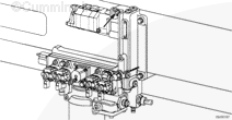
| Guided Step 3B – Check the fuel inlet restriction. | ||
|---|---|---|
Conditions
ActionIf the engine uses a fuel lift pump, wait until after priming pump has turned off and observe the reading on the vacuum gauge. |
|
|
|
Is fuel inlet restriction less than the specifications listed below?
|
||
| YES | NO | |
| No Repair |
Locate the cause of high fuel inlet restriction. Check the suction-side fuel filter and fuel supply lines. |
|
|
Repair complete
|
||
| Guided Step 3C – Check the drain line restriction. | ||
|---|---|---|
Conditions
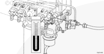
ActionObserve the reading on the pressure gauge. |
|
|
|
Is fuel drain line restriction less than 229 mm Hg [9 in Hg]? |
||
| YES | NO | |
| No Repair |
Locate the cause of the high fuel drain line restriction in the OEM fuel return line. |
|
|
Repair complete
|
||
| Guided Step 3D – Check the fuel grade. | |
|---|---|
Conditions
ActionVerify the fuel grade used is appropriate for the application and ambient conditions and fuel quality is acceptable. Run the engine on an alternate, known good fuel source and verify engine performance if the fuel can not be tested appropriately. NOTE: Refer to Fuel for Cummins Engines, Bulletin 3379001. |
|
|
Is the fuel grade used and the quality acceptable? |
|
| YES | NO |
| No Repair |
Instruct the driver or owner to refuel with acceptable fuel. |
|
Repair complete
|
|
| Guided Step 3E – Perform the INSITE™ electronic service tool Cylinder Performance Test. | |
|---|---|
Conditions
ActionPerform the INSITE™ Cylinder Performance Test. NOTE: Do not run the engine above 900 rpm when performing the Cylinder Performance Test. |
|
|
Do all injectors and both banks pass the Cylinder Performance Test? |
|
| YES | NO |
| No Repair | No Repair |
| Guided Step 3E-1 – Interpret the results of the Cylinder Performance Test. | |
|---|---|
ActionInterpret the results of the INSITE™ Cylinder Performance Test.
|
|
|
Did the Cylinder Performance Test find an individual failed cylinder? |
|
| YES | NO |
|
Replace the failed injector. Refer to Procedure 006-026 in the Troubleshooting and Repair Manual, Signature, ISX, and QSX15 Engines, Bulletin 3666239. |
No Repair |
|
Repair complete
|
|
| Guided Step 3E-2 – Interpret the results of the Cylinder Performance Test. | |
|---|---|
ActionInterpret the results of the INSITE™ Cylinder Performance Test.
|
|
|
Did the Cylinder Performance Test find an individual failed bank? |
|
| YES | NO |
| No Repair | No Repair |
| Guided Step 3E-3 – Measure the resistance between the actuator and the actuator base. | ||
|---|---|---|
Conditions
ActionMeasure the resistance between the actuator and the actuator mounting base. |
|
|
|
Greater than 100k ohms? |
||
| YES | NO | |
| No Repair |
Replace the failed fueling or timing actuator. |
|
|
Repair complete
|
||
| Guided Step 3E-4 – Swap the front and rear fueling actuators. | |
|---|---|
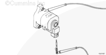
ActionSwap the front and rear fueling actuators to determine if the failed bank of cylinders follows the actuator.
|
|
|
Does the failed bank follow the metering actuator? |
|
| YES | NO |
|
Replace the failed fueling actuator. Refer to Procedure 019-110. |
No Repair |
|
Repair complete
|
|
| Guided Step 3E-5 – Swap the front and rear timing actuators. | |
|---|---|
ActionSwap the front and rear timing actuators to determine if the failed bank of cylinders follows the timing actuator.
|
|
|
Does the failed bank follow the timing actuator? |
|
| YES | NO |
|
Replace the failed timing actuator. Refer to Procedure 019-111. |
Troubleshooting procedures need to be repeated from the beginning. A failed injector or actuator should have been detected. |
|
Repair complete
|
|
Guided Step 4 – Check the air handling system.
| Guided Step 4A – Check the air intake restriction. | |
|---|---|
Conditions
ActionCheck the intake system restriction by installing a vacuum gauge or water manometer into the air intake system. Refer to Procedure 010-031 in the Troubleshooting and Repair Manual, Signature, ISX, and QSX15 Engines, Bulletin 3666239. |
|
|
Is air intake restriction greater than 635 mm H2O [25 in H2O] for a used filter or 254 in H2O [10 in H2O] for a new filter? |
|
| YES | NO |
|
Correct the cause of high intake air restriction. Check for plugged air filter or restricted air intake piping. |
No Repair |
|
Repair complete
|
|
| Guided Step 4B – Pressure test the charge air cooler. | |
|---|---|
Conditions
ActionPressure test the charge air cooler. Refer to Procedure 010-027 in the Troubleshooting and Repair Manual, Signature, ISX, and QSX15 Engines, Bulletin 3666239. |
|
|
Is the pressure drop 5 psi or less in 15 seconds? |
|
| YES | NO |
| No Repair |
Repair the charge air cooler. |
|
Repair complete
|
|
| Guided Step 4C – Inspect the charge air cooler. | |
|---|---|
Conditions
ActionInspect the charge air cooler for bent or plugged fins. Bent or plugged fins will force the temperature of the air exiting the cooler to raise and force the engine to work harder to obtain the desired charge flow. A harder working engine will use more fuel. |
|
|
Is the charge air cooler free from bent or plugged fins? |
|
| YES | NO |
| No Repair |
Clean the charge air cooler. |
|
Repair complete
|
|
| Guided Step 4D – Check the exhaust restriction. | |
|---|---|
Conditions
ActionCheck the exhaust restriction by installing a pressure gauge into the exhaust system just past the turbocharger. Refer to Procedure 011-009 in the Troubleshooting and Repair Manual, Signature, ISX, and QSX15 Engines, Bulletin 3666239. |
|
|
Is exhaust restriction less than 76 mm Hg [3 in Hg]? |
|
| YES | NO |
| No Repair |
Repair the exhaust for source of high restriction. |
|
Repair complete
|
|
Guided Step 5 – Air handling diagnostic checks.
| Guided Step 5A – Start the engine and read the fault codes. | |
|---|---|
Conditions
ActionCheck the fault codes with the engine running. Use INSITE™ electronic service tool to read the fault codes. |
|
|
Are Fault Codes 2355 or 2356 active? |
|
| YES | NO |
| No Repair | No Repair |
|
Go to appropriate Fault Code troubleshooting tree.
|
|
| Guided Step 5B – Inspect the turbocharger blades. | |
|---|---|
Conditions
ActionInspect the compressor and turbine fins for damage or wear. Measure the turbocharger wheel axial movement. Check the radial movement of the turbocharger wheel. Refer to Procedure 010-033 in the Troubleshooting and Repair Manual, Signature, ISX, and QSX15 Engines, Bulletin 3666239. |
|
|
Was damage found on turbocharger fins or was axial or radial movement out of specification? |
|
| YES | NO |
|
Replace the turbocharger. Refer to Procedure 010-033 in the Troubleshooting and Repair Manual, Signature, ISX, and QSX15 Engines, Bulletin 3666239. |
No Repair |
|
Repair complete
|
|
| Guided Step 5C – Determination of turbocharger type. | |
|---|---|
ActionDetermine if the turbocharger is a wastegated or variable geometry turbocharger. |
|
|
Is the turbocharger a variable geometry turbocharger? |
|
| YES | NO |
| No Repair | No Repair |
| Guided Step 5D – Check the variable geometry actuator rod for correct travel. | ||
|---|---|---|
Conditions
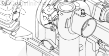
ActionPerform the Turbocharger Actuator Test using the INSITE™ electronic service tool.
NOTE: The turbocharger actuator should move quickly and crisply. If the actuator rod movement is slow, there could be a problem with the air supply, a faulty ground connection on the engine or chassis, or mechanical problems with the variable geometry turbocharger assembly. |
|
|
|
Does the turbocharger actuator rod extend between 10.2 and 11.8 mm [0.402 and 0.465 in]? |
||
| YES | NO | |
| No Repair | No Repair | |
| Guided Step 5D-1 – Check for air leaks and inspect air lines. | |
|---|---|
Conditions
ActionPerform the Turbocharger Actuator Test using the INSITE™ electronic service tool. Select the Extend Actuator position. Listen for air leaks at the following components:
|
|
|
Air leaks found in the system? |
|
| YES | NO |
|
Repair air leaks. |
No Repair |
|
Repair complete
|
|
| Guided Step 5D-2 – Check the engine and vehicle grounds. | ||
|---|---|---|
Conditions
ActionCheck for loose or corroded engine, chassis, or battery ground connections.
|
|
|
|
Are all grounds present, properly grounded, free of corrosion, and tight? |
||
| YES | NO | |
| No Repair |
Replace, clean, or tighten the ground. |
|
|
Repair complete
|
||
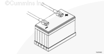
| Guided Step 5D-3 – Check for air pressure at the turbocharger control valve outlet. | |
|---|---|
Conditions
ActionPerform the Turbocharger Actuator Test using the INSITE™ electronic service tool. Select the Retract Actuator position. Remove the air line connection at the outlet of the turbocharger control valve. Install an M12 Compucheck® fitting, Part Number 3824843, at the outlet of the turbocharger control valve. Install an air pressure gauge that is capable of reading at least 1034 kPa [150 psi] Perform the Turbocharger Actuator Test using the INSITE™ electronic service tool. Select the Extend Actuator position. |
|
|
Is vehicle air tank pressure present at the turbocharger control valve outlet? |
|
| YES | NO |
| No Repair | No Repair |
| Guided Step 5D-4 – Check for air pressure at the turbocharger control valve outlet. | |
|---|---|
Conditions
ActionPerform the Turbocharger Actuator Test using the INSITE™ electronic service tool. Select the Retract Actuator position. Remove the air line connection at the outlet of the turbocharger control valve. Install an M12 Compucheck® fitting at the outlet of the turbocharger control valve. Install an air pressure gauge that is capable of reading at least 1034 kPa [150 psi]. |
|
|
Does the pressure gauge read more than 15 psi after 5 minutes? |
|
| YES | NO |
|
Replace the turbocharger control valve. Refer to Procedure 019-388. |
No Repair |
|
Repair complete
|
|
| Guided Step 5D-5 – Check for correct turbocharger actuator travel. | ||
|---|---|---|
Conditions
ActionRemove the Variable Geometry Actuator from the turbocharger. Refer to Procedure 010-113 in the Troubleshooting and Repair Manual, Signature, ISX, and QSX15 Engines, Bulletin 3666239. NOTE: Damage to the turbocharger may result if the proper removal procedure is not followed. Perform the Turbocharger Actuator Test using the INSITE™ electronic service tool. Select the Extend Actuator position. |
|
|
|
Does the turbocharger actuator rod travel at least 12 mm [0.472 in]? |
||
| YES | NO | |
|
Replace the turbocharger assembly. Refer to Procedure 010-033 in the Troubleshooting and Repair Manual, Signature, ISX, QSX Engines, Bulletin 3666239. |
Replace the turbocharger actuator. Refer to Procedure 010-113 in the Troubleshooting and Repair Manual, Signature, ISX, and QSX15 Engines, Bulletin 3666239. |
|
|
Repair complete
|
Repair complete
|
|
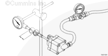
| Guided Step 5D-6 – Check for air pressure at the turbocharger control shutoff valve outlet. | ||
|---|---|---|
Conditions
ActionUse INSITE™ to start the Turbocharger Actuator Test. Loosen the air line connection at the turbocharger control shutoff valve outlet. |
|
|
|
Can air be heard escaping from the turbocharger control shutoff valve outlet? |
||
| YES | NO | |
|
Replace the turbocharger control valve. Refer to Procedure 019-388. |
No Repair | |
|
Repair complete
|
||
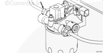
| Guided Step 5D-7 – Check for air pressure at the turbocharger control shutoff valve inlet. | |
|---|---|
Conditions
ActionVerify the OEM air supply line is connected to the correct port on the turbocharger control shutoff valve. Loosen the air line connection at the turbocharger control shutoff inlet. |
|
|
Can air be heard escaping from the turbocharger control shutoff valve inlet? |
|
| YES | NO |
| No Repair |
Repair the air supply from the OEM air tanks. |
|
Repair complete
|
|
| Guided Step 5D-8 – Check for plugged turbocharger control shutoff valve filter. | |
|---|---|
Conditions
ActionUse INSITE™ to start the Turbocharger Actuator Test. Listen for an air leak at the turbocharger control shutoff valve filter head. |
|
|
Is an air leak present at the turbocharger control shutoff valve filter head? |
|
| YES | NO |
|
Replace the turbocharger control shutoff valve filter. Refer to Procedure 010-114 in the Troubleshooting and Repair Manual, Signature, ISX, and QSX15 Engines, Bulletin 3666239. |
Replace the turbocharger control shutoff valve. Refer to Procedure 019-386. |
|
Repair complete
|
Repair complete
|
| Guided Step 5E – Perform the INSITE™ electronic service tool EGR Valve/Turbocharger Operational Test. | |
|---|---|
Conditions
ActionSelect the EGR/VGT™ Operational Test using the INSITE™ electronic service tool. NOTE: Prior to running the INSITE™ electronic service tool EGR Valve and EGR Valve/Turbocharger Operational Test, the ECM Calibration Software Phase could possibly need to be updated to the latest Software Phase. The ECM Calibration Phase Software can be checked in INSITE™ electronic service tool, under ‘Features and Parameters’. Expand the selection for ‘System ID and Dataplate’ and go to ‘Calibration Information’. If the Software Phase is earlier than shown below, recalibrate the ECM using the January 2006 INCAL™ CD-ROM, or later. Engines with the Software Phase listed below or later do not require a recalibration. ISX engines with CM870 (engines built after January 2004) require Software Phase 06050302. ISX engines with CM870 (engines built before January 2004) require no changes at this time. This is a warrantable calibration change. Choose the Turbocharger Actuator option under Test Choices. |
|
|
Does the Turbocharger Operational Test pass? |
|
| YES | NO |
| No Repair | No Repair |
| Guided Step 5E-1 – Check the engine and vehicle grounds. | ||
|---|---|---|
Conditions
ActionCheck for a loose or corroded engine, chassis, or battery ground connection.
|
|
|
|
Are all grounds present, properly grounded, free of corrosion, and tight? |
||
| YES | NO | |
|
Replace the variable geometry turbocharger. Refer to Procedure 010-033 in the Troubleshooting and Repair Manual, Signature, ISX, QSX Engines, Bulletin 3666239. |
Replace, clean, or tighten the ground. |
|
|
Repair complete
|
Repair complete
|
|
| Guided Step 5F – Inspect the wastegate actuator hose. | ||
|---|---|---|
Conditions
ActionInspect the integral wastegate actuator hose for cracks or holes. |
|
|
|
Are holes or cracks found in the wastegate actuator hose? |
||
| YES | NO | |
|
Replace the wastegate actuator hose. |
No Repair | |
|
Repair complete
|
||
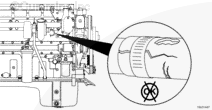
| Guided Step 5G – Inspect the wastegate actuator rod for travel. | ||
|---|---|---|
Conditions
ActionApply a regulated air supply of 310 kPa [45 psi] to the actuator and check for actuator movement. |
|
|
|
Does the wastegate actuator rod move? |
||
| YES | NO | |
| No Repair | No Repair | |
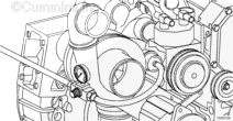
| Guided Step 5G-1 – Inspect the wastegate actuator rod for travel. | ||
|---|---|---|
Conditions
ActionApply a regulated air supply of 310 kPa [45 psi] to the actuator and check for actuator movement. |
|
|
|
Does the wastegate actuator rod move? |
||
| YES | NO | |
|
Move the wastegate lever on the turbocharger back and forth and check for smooth operation. Replace the turbocharger assembly if the wastegate is seized. Refer to Procedure 010-033 in the Troubleshooting and Repair Manual, Signature, ISX, and QSX15 Engines, Bulletin 3666239. |
Replace the wastegate actuator. Refer to Procedure 010-050 in the Troubleshooting and Repair Manual, Signature, ISX, and QSX15 Engines, Bulletin 3666239. |
|
|
Repair complete
|
Repair complete
|
|
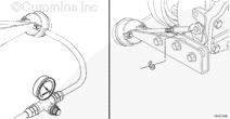
| Guided Step 5H – Measure the resistance of the four-stage wastegate controllers, if equipped. | |
|---|---|
Conditions
ActionMeasure the resistance from the wastegate controller post to engine block ground. NOTE: The wastegate controller solenoids must be between 20°C and 26°C [68°F and 78°F] before using the resistance specifications listed. |
|
|
Are the wastegate controller solenoid resistances between 7.0 and 8.0 ohms? |
|
| YES | NO |
| No Repair |
Replace the failed wastegate controller. Refer to Procedure 010-109 in the Troubleshooting and Repair Manual, Signature, ISX, QSX Engines, Bulletin 3666239. |
|
Repair complete
|
|
| Guided Step 5I – Inspect the four-stage wastegate controller, if equipped. | ||
|---|---|---|
Conditions
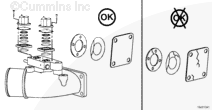
ActionCheck the valve disc, valve seat, and actuator disc for dirt, metal, debris, bonding separation, corrosion, cracks, or wear. |
|
|
|
Damage or debris found on the valve disc, valve seat, or actuator disc? |
||
| YES | NO | |
|
Replace or clean failed components. |
No Repair | |
|
Repair complete
|
||
Guided Step 6 – Base engine checks.
| Guided Step 6A – Verify the overhead adjustments are correct. | |
|---|---|
Conditions
ActionMeasure the overhead settings. Valve Lash Reuse Limits:
|
|
|
Are the overhead settings within the reuse limits? |
|
| YES | NO |
| No Repair |
Adjust the overhead settings. Refer to Procedure 003-004 in the Troubleshooting and Repair Manual, Signature, ISX, QSX Engines, Bulletin 3666239. |
|
Repair complete
|
|
| Guided Step 6B – Verify the dipstick calibration. | |
|---|---|
Conditions
ActionVerify the dipstick calibration. Drain, remove, clean, and install the lubricating oil pan. Refer to Procedure 007-025 in the Troubleshooting and Repair Manual, Signature, ISX, and QSX15 Engines, Bulletin 3666239. Check the calibration of the lubricating oil dipstick. Refer to Procedure 007-009 in the Troubleshooting and Repair Manual, Signature, ISX, and QSX15 Engines, Bulletin 3666239. |
|
|
Is the dipstick calibrated properly? |
|
| YES | NO |
| No Repair |
Calibrate the lubricating oil dipstick. Refer to Procedure 007-009 in the Troubleshooting and Repair Manual, Signature, ISX, and QSX15 Engines, Bulletin 3666239. |
|
Repair complete
|
|
| Guided Step 6C – Analyze the engine oil. | |
|---|---|
Conditions
ActionTake an engine oil sample. |
|
|
Does the engine oil analysis show any signs of wear metals or contaminates? |
|
| YES | NO |
| No Repair |
Locate and replace the worn component or remove the source of contaminate and repair the engine as necessary. |
|
Repair complete
|
|
| Guided Step 6D – Check for internal engine damage. | |
|---|---|
Conditions
ActionRemove the oil filter. Inspect and replace the oil filter. Refer to Procedure 007-013 in the Troubleshooting and Repair Manual, Signature, ISX, and QSX15 Engines, Bulletin 3666239. |
|
|
Is any foreign material found in the oil filter? |
|
| YES | NO |
|
Locate the source of foreign material and repair the engine as necessary. |
No Repair |
|
Repair complete
|
Return to the troubleshooting steps or contact a local Cummins Authorized Repair Location, if all steps have been completed and checked again.
|

;)
;)
;)
;)
;)
;)
;)
;)
;)
;)
;)
;)
;)
;)
;)
;)
;)
;)
;)
;)
;)
;)