Batteries can emit explosive gases. To reduce the possibility of personal injury, always ventilate the compartment before servicing the batteries. To reduce the possibility of arcing, remove the negative (-) battery cable first and attach the negative (-) battery cable last.
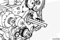
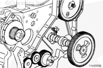
NOTE: On Marine applications, prior to starting this procedure, make sure that there is adequate clearance in front of the engine. This procedure requires the camshaft to be removed. Make sure there is adequate clearance from the front gear housing face to any obstruction in the camshaft area to remove the camshaft. If there is not enough clearance, the engine must be removed from the vessel.
Use tappet removal tool kit, Part Number 3822513, to remove the tappets.
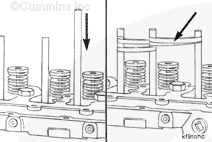
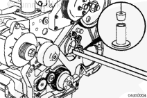
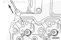
Push a wooden dowel rod into each tappet. It will probably be necessary to push the dowel into the tappet with a soft-face hammer.
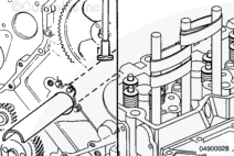
Pull each valve tappet up until it makes contact with the cylinder block. Put a rubber band around two dowels. This will hold the tappets up off the camshaft.
Only remove one (1) tappet at time. Remove the rubber band from the two (2) companion tappets, securing the tappet not to be removed with the rubber band.
When the tappet is dropped into the trough, most of the time it will fall over. However, if it doesn’t, gently shake the trough just enough to allow the tappet to fall over before removing.
Use tappet removal tool kit, Part Number 3165088, to remove the tappets.
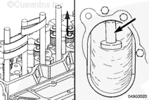
Insert the tappet extractor tool (2) into the tappet bore. Turn the top knob counterclockwise while holding the bottom knob to expand and secure the tool into the tappet.
Raise the tappet extractor (2) until it stops, and push the metal tab down against the head surface to secure the tool and captured tappet in the up position.
Lower the tappet extractor, and seat the tappet into the tappet holder. Turn the top knob clockwise while holding the bottom knob to disengage the extractor from the tappet. Repeat the step for the remaining tappets.
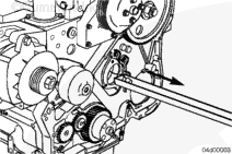
Carefully pull the tappet holder and tappets from the camshaft bore. If the tappets will be reused, be sure to note their position. Do not install a tappet in a different position.
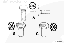
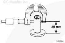
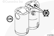
Inspect the tappet body for cracks or other damage.
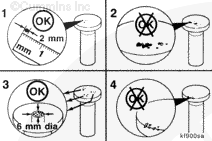
Inspect the roller for flat spots or pitting. Refer to Camshaft Reuse Guidelines for Cummins® Engines with Roller Followers or Roller Tappets, Bulletin 3666052. If excessive wear is found, replace the tappet, and inspect the camshaft.
The roller must rotate freely. If it does not, replace the tappet.
Anytime a camshaft or tappets are replaced in a B or C series engine with sliding tappets, that has more than 250 hours or 5000 miles, the camshaft, tappets, and push tubes must be replaced with new.
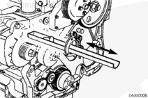
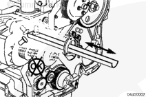
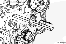
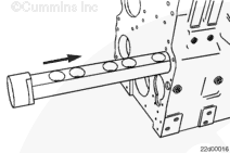
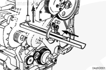
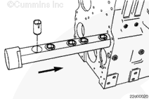
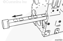
Insert the trough the full length of the camshaft bore.
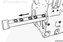
Feed the installation tool through the camshaft bores by carefully pulling the plastic trough or installation tool out the front. The barrier at the rear of the trough will pull the tool out most of the time.
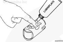
To aid in removing the installation tool after the tappet is installed, work the tool in and out of the tappet several times before installing the tappets.
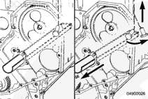
If difficulty is experienced in getting the tappet to make the bend from the trough up to the tappet bore, pull the trough out enough to allow the tappet to drop down and align itself, then pull the tappet up into the bore.
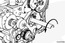
After the tappet has been pulled up into position, slide the trough back into the camshaft bore and rotate it one-half turn. This will position the round side of the trough up, and will hold the tappet in place.
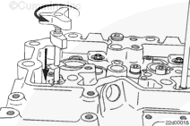
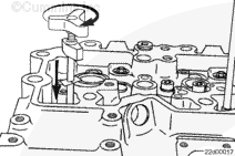
Insert the tappet extractor tool (2) into the tappet bore. Turn the top counterclockwise to expand and secure the tool into the tappet.
Raise the tappet extractor (2) until it stops, and push the metal tab down against the head surface to secure the tool in the up position.
NOTE: Some manipulation may be necessary to get the tappet to enter the bore. When the tappet enters the bore, attempt to rotate the extractor while applying light upward pressure. If the tool will not rotate, the tappet has engaged the guide pin. If the tool does rotate, continue until the tappet engages the guide pin.
Lower the tappet extractor, and seat the tappet into the camshaft. Turn the top knob clockwise while holding the bottom knob to disengage the extractor from the tappet. Repeat the step for the remaining tappets.
Batteries can emit explosive gases. To reduce the possibility of personal injury, always ventilate the compartment before servicing the batteries. To reduce the possibility of arcing, remove the negative (-) battery cable first and attach the negative (-) battery cable last.
Hello, I'm Jack, a diesel engine fan and a blogger. I write about how to fix and improve diesel engines, from cars to trucks to generators. I also review the newest models and innovations in the diesel market. If you are interested in learning more about diesel engines, check out my blog and leave your feedback.
View all posts by Jack
 WARNING





 CAUTION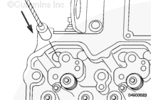

;)
;)
;)
;)
;)
;)
;)
;)
;)
;)
;)
;)
;)
;)
;)
;)
;)
;)
;)
;)
;)
;)
;)
;)
;)
;)
;)
;)
;)
;)
;)
;)
;)
;)
;)
;)
;)
;)
;)
;)
;)
;)
;)
;)
;)
;)
;)
;)
;)
;)
;)
;)
;)
;)
;)
;)
;)
;)
