Batteries can emit explosive gases. To reduce the possibility of personal injury, always ventilate the compartment before servicing the batteries. To reduce the possibility of arcing, remove the negative (-) battery cable first and attach the negative (-) battery cable last.
WARNING
Do not remove the pressure cap from a hot engine. Wait until the coolant temperature is below 50°C [120°F] before removing the pressure cap. Heated coolant spray or steam can cause personal injury.
WARNING
Coolant is toxic. Keep away from children and pets. If not reused, dispose of in accordance with local environmental regulations.
WARNING
Air pressure must be released from the system before removing the air governor. The governor can be under pressure and cause personal injury.
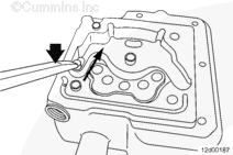
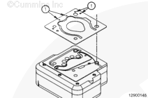
Do not remove the three M6 internal hex capscrews at this time.
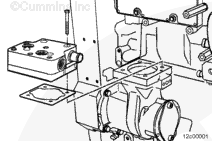
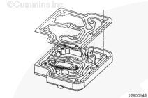
Remove the head and gasket.
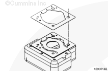
NOTE: Due to an interference with the fuel pump on some applications, it can be difficult to remove all four mounting capscrews completely from the air compressor cylinder head while the air compressor is still mounted to the engine. To remove the cylinder head, completely remove the front two capscrews and completely loosen the rear two capscrews. Simultaneously lift the left rear capscrew and cylinder head to unseat the locating dowel from the air compressor housing. Slowly rotate the head counterclockwise, using the right rear locating dowel as a pivot point until enough clearance is available to lift the cylinder head off of the air compressor.
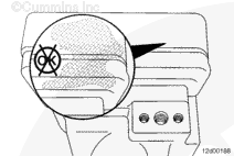
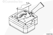
Inspect the cylinder head for signs of an external coolant leak. A large coolant leak from the air compressor cylinder head will have blistered/removed paint and/or have a white deposit build up.
If a large coolant leak is observed, the head should be rebuilt with a gasket kit. Refer to the Cylinder Head Gasket Kit in the Install section.
Inspect the unloader valve plate and cylinder head for deep scratching or scoring. If the cylinder head is scratched or scored deeply, it must be replaced.
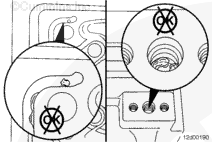
Verify that the unloader piston is in the proper orientation and operates properly. If, upon inspection, the unloader piston and plate are stuck open, exposing any area of the relief chamber, carefully remove the unloader plate from the unloader piston pinions.
NOTE: The unloader piston and plate must always default to the fully closed position.
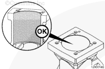
Place a few drops of automatic transmission fluid into the unloader piston bore. Coat the front and back side of the piston with fluid.
Use a stiff wooden handle to apply pressure to the unloader valve against the spring. Slide the unloader piston through the full range of rearward travel. When the spring is fully compressed, quickly let the pressure off, allowing the spring to drive the piston back to its closed state. Repeat cycling the unloader piston in this manner 5 to 10 times.
If the unloader piston continues to demonstrate any resistance to movement, or slow response while returning to the default closed position, the cylinder head must be replaced.
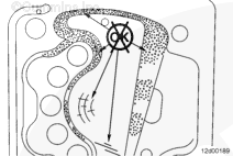
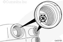
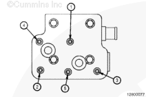
Inspect the unloader channel and governor supply port, as well as the unloader piston, for signs of rust.
NOTE: Rust present in the unloader channel and/or governor feed port indicates that either the air dryer has malfunctioned, or improper draining of the vehicle air tanks. Use the following procedure to check the air governor for proper operation. Refer to Procedure 012-016 in Section 12. Refer to the OEM service manual for troubleshooting the air dryer, as well as proper maintenance intervals for the vehicle compressed air tanks.
While the air compressor cylinder head is removed, inspect the rotating components and the cylinder bore of the air compressor for damage. Refer to Procedure 012-014 in Section 12.
NOTE: If installing a new air compressor cylinder head assembly, the following steps should not be performed. New cylinder head assemblies are already assembled per the instructions below. Skip to placement of the cylinder head assembly onto the air compressor housing.
Apply a light coating of assembly lubricant, Part Number 3163087 or equivalent, to the unloader plate recess of the cylinder head.
Place the unloader plate onto the unloader piston pinion, as well as the stationary pinion, and press the unloader plate into the assembly lubricant.
NOTE: A new gasket kit must be used each time the air compressor cylinder head is removed and installed. Do not reuse the cylinder head mounting capscrews.
NOTE: Due to an interference with the fuel pump on some applications, following a specific installation sequence of the air compressor cylinder head and mounting capscrews will make installation possible with the air compressor still installed on the engine.
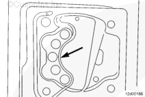
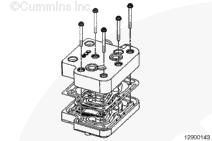
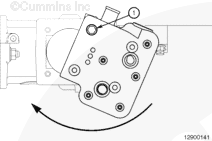
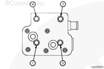
Before placing the cylinder head on the air compressor housing, insert the rear right capscrew (1) through the mounting hole. Place the cylinder head on the air compressor housing such that the right rear locating dowel and mounting capscrew engage the mounting hole in the air compressor housing.
Insert the rear left capscrew through the cylinder head mounting hole. Rotate the cylinder head clockwise into position, using the rear right capscrew and locating dowel as a pivot. Once the cylinder head has been properly set onto the air compressor housing, insert the front two capscrews.
Batteries can emit explosive gases. To reduce the possibility of personal injury, always ventilate the compartment before servicing the batteries. To reduce the possibility of arcing, remove the negative (-) battery cable first and attach the negative (-) battery cable last.
Install the air inlet and outlet connections from the air compressor.
Install the air governor or air governor signal line, if necessary. Refer to the OEM service manual.
Hello, I'm Jack, a diesel engine fan and a blogger. I write about how to fix and improve diesel engines, from cars to trucks to generators. I also review the newest models and innovations in the diesel market. If you are interested in learning more about diesel engines, check out my blog and leave your feedback.
View all posts by Jack
 WARNING


;)
;)
;)
;)
;)
;)
;)
;)
;)
;)
;)
;)
;)
;)
;)
;)
;)
;)
;)
;)
;)
;)
;)
;)
;)
;)
;)
;)
;)
;)
;)
;)
;)
;)