This test checks for combustion gas leaks back through the injector rail check valve, or other conditions that will allow gas leakage through the injector into the fuel rail.
When the engine is barred over, back pressure is created against the injector by the piston coming up on the compression stroke.
During the test, if the rail check valve is leaking, air is pushed through the rail check valve and into the fuel rail, where pressure is sensed at the test fixture which is in place of the metering actuator. If a manometer is connected to the test fixture, pressure will be measured as air escapes through the leaking rail check valve. If a container of water is used instead of a manometer, bubbles will be seen as air escapes through the leaking rail check valve.
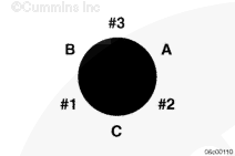
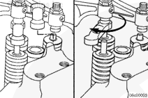
The overhead set marks on the damper are used to identify which cylinder is on the compression stroke, and therefore which injector has malfunctioned, if a change in manometer pressure or bubbles are seen.
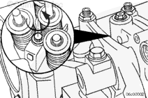
The fuel-metering actuators are the actuators located on each end of the unit.
Remove the fuel-metering actuator for the front three cylinders. Use the ISX Fuel System Troubleshooting and Repair Manual, Bulletin 3666259. Refer to Procedure 019-110 in Section 19.
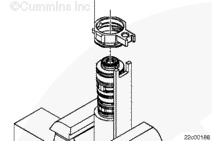
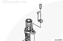
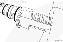
Install the Injector Leak Test Kit, Part Number 3164001, in place of the fuel-metering actuator.
Torque Value: 15.3 n.m [135 in-lb]
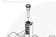
Connect the flexible tubing to the hose fitting on the mounting plate.
Place the flexible tubing into a container of water.
Do not crank the engine for more than 20 seconds and allow 2 minutes between crank cycles for the starter to cool. Failure to do so can result in starting motor component damage.
Remove the 4-pin power connector from the ECM and then crank the engine. Disconnecting the 4-pin power connector will prevent the engine from starting.
NOTE: For engines without 4-pin power connectors on the ECM, disconnect the fuel shutoff solenoid supply wire from the fuel shutoff solenoid and then crank the engine. Disconnecting the fuel shutoff solenoid supply wire will prevent the engine from starting.
If bubbles are observed in the container, proceed with barring over the engine to determine which injector is leaking.
If no bubbles are observed in the container, there is no leak in the bank. Continue with this procedure.
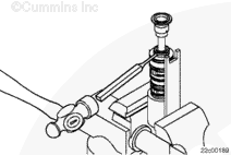
Bar the engine over while watching for bubbles in the container.
The engine will need to be barred over two complete revolutions to evaluate each bank.
There can be a few bubbles observed immediately before reaching a timing mark. The leak indicator is if bubbles occur for an extended period between the timing marks.
Remove the mounting plate connected to the port for the front three cylinders. Install the fuel-metering actuator removed previously. Use the ISX Fuel System Troubleshooting and Repair Manual, Bulletin 3666259. Refer to Procedure 019-110 in Section 19.
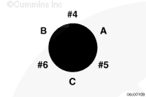
Remove the fuel-metering actuator for the rear three cylinders.
Install the Injector Leak Test Kit, Part Number 3164001, in place of the rear fuel-metering actuator.
Torque Value: 15.3 n.m [135 in-lb]
Place the flexible tubing into a container of water.
Repeat the above procedure for the rear three cylinders.
Do not remove the pressure cap from a hot engine. Wait until the coolant temperature is below 50°C [120°F] before removing the pressure cap. Heated coolant spray or steam can cause personal injury.
WARNING
Coolant is toxic. Keep away from children and pets. If not reused, dispose of in accordance with local environmental regulations.
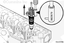
Do not use a heel bar to pry the injector loose from the cylinder head. Damage to the injector can occur.
Use injector puller, Part Number 3823579, to remove the injectors.
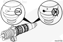
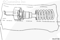
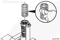
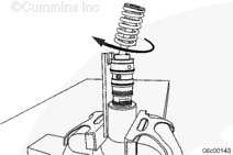
If the injector spring does come loose from the spring retainer, it can be reassembled by using a screwdriver to compress the spring back under the retainer.
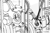
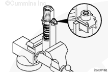
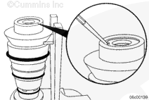
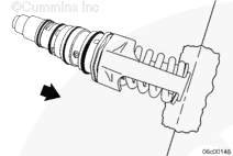
Its very important that a 3/32 inch punch be used so the barrel is not damaged during oil seal removal.
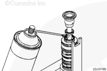
Use a 3/32 inch punch. Place the punch at an upward angle, as shown in the illustration, against the base of the oil seal.
Use a hammer to gently tap the punch against the base of the oil seal. To prevent damage to the seal bore in the barrel, alternate between the four holes in the barrel so that the seal comes out evenly and does not score the barrel.
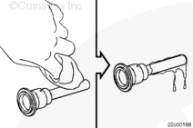
Thoroughly clean the oil and dirt from the outside of the injector.
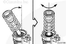
Place a clean, lint-free shop towel folded in quarters over the edge of a work bench.
While holding the injector firmly in one hand, place the upper plunger against the outer edge of the work bench with the load ring just above the working surface of the bench.
Lean in on the injector to partially compress the upper spring and plunger. Use care not to come in contact with the nozzle of the injector.
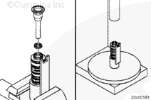
With the new oil seal positioned on the tool, position the tool over the seal bore.
Use the arbor press to gently place pressure onto the installation tool until the outer diameter face of the tool contacts the injector body.
When properly installed, the seal height will not be flush with the injector body. The height will be approximately 0.5 mm [0.020 in] above the injector.
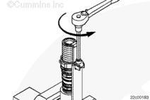
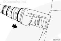
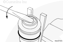
Install a new roll pin into the load ring. By design, the roll pin holes are a different size on each side, so the roll pin must be installed in the correct direction, as illustrated.
Use a 5/32 inch punch to gently tap the roll pin into both holes in the load ring. Continue driving the roll pin into the load ring until the pin is centered evenly in both holes and is an equal distance from both sides.
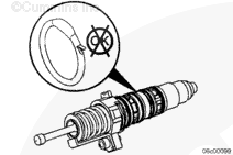
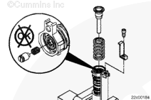
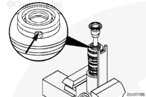
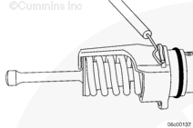
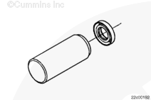
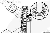
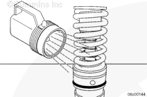
Use a flashlight to view through the coupling spring. Inspect the oil seal to verify the garter spring (1) is still in the correct location around the seal.
With the new oil seal positioned on the tool, position the tool over the seal bore.
Use the arbor press to gently place pressure onto the installation tool until the outer diameter face of the tool contacts the injector body.
When properly installed, the seal height will not be flush with the injector body. The height will be approximately 0.5 mm [0.020 in] above the injector.
Use a flashlight to view through the coupling spring. Inspect the oil seal to verify the garter spring is still in the correct location around the seal.
Place a clean, lint free shop towel folded in quarters over the edge of a work bench.
While holding the injector firmly in one hand, place the upper plunger against the outer edge of the work bench with the load ring just above the working surface of the bench.
Lean in on the injector to partially compress the upper spring and plunger. Use care not to come in contact with the nozzle of the injector.
Make sure the injector hold down clamp is properly aligned before tightening the capscrew. It is possible for the clamp to contact a nearby ledge, and result in low clamp load.
Install the injector into the cylinder head.
Install the injector clamp and the capscrew with washer.
Operate the engine to normal operating temperature and check for leaks.
If damage resulted in coolant, oil, excessive fuel or excessive black smoke entering the exhaust system, the aftertreatment system must be inspected. Refer to Procedure 014-013 in Section 14.
Hello, I'm Jack, a diesel engine fan and a blogger. I write about how to fix and improve diesel engines, from cars to trucks to generators. I also review the newest models and innovations in the diesel market. If you are interested in learning more about diesel engines, check out my blog and leave your feedback.
View all posts by Jack


 CAUTION
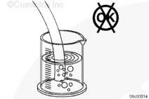


 WARNING


;)
;)
;)
;)
;)
;)
;)
;)
;)
;)
;)
;)
;)
;)
;)
;)
;)
;)
;)
;)
;)
;)
;)
;)
;)
;)
;)
;)
;)
;)
;)
;)
;)
;)
;)
;)
;)
;)
;)
;)
;)
;)
;)
;)
;)
;)
;)
;)
;)
;)
;)
;)
;)
;)
;)
;)
;)
;)
;)
;)
;)
;)
;)
;)
;)
;)
;)
;)
;)
;)
;)
;)
;)
;)
;)
;)
;)
;)
;)
;)
;)
;)
;)
;)
;)
;)
;)
;)
;)
;)
;)
;)
;)
;)