The following procedure covers common troubleshooting steps to help identify:
Engine overheating causes. See the Initial Check section of this procedure.
NOTE: At the end of this procedure, a worksheet is provided to record any measured values taken during troubleshooting. The worksheet will help in gathering and analyzing the data.
External and internal coolant leaks/loss. See the Pressure Test section of this procedure.
Combustion gas leaks into the cooling system. See the Test section of this procedure.
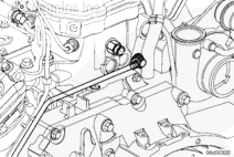
If the coolant reaches an unacceptable level in the recovery/expansion tank, a fault code should become active that will illuminate an instrument lamp and impose a power derate. This low level is detected by a coolant level switch mounted in the coolant surge/recovery tank.
In the event of a cooling system-related malfunction, it is recommended that the coolant level switches be checked for proper operation. Refer to the OEM service manual for operational checks and repairs.
Removal and installation of the coolant level switch for diagnostics is NOT recommended. This poses a high likelihood of damage, due to the plastic construction of the switch. The coolant level switch must only be removed from the surge/recovery tank when replacing it with a new switch. Be certain not to overtighten the switch when installing. Most switches have a very low torque value, which can be found in the OEM service manual.
Coolant level switches are very susceptible to improper pH levels. For this reason, it is imperative that coolant be maintained in accordance with Cummins® Coolant Requirements and Maintenance, Bulletin 3666132.
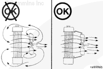
Never operate the engine without a thermostat. Without a thermostat, the path of least resistance for the coolant is through the bypass to the water pump inlet. This can cause the engine to overheat.
Thermostat
There are different temperature range thermostats available, depending on the engine type and application. The part number and nominal operating temperature are stamped on the thermostat. To verify that the correct temperature range and part number thermostat is installed, make sure to reference the appropriate part information resources. Refer to Procedure 008-013 in Section 8.
A damaged or an incorrect water pump can lead to an engine overheating condition. To verify that the correct water pump is installed, make sure to reference the appropriate parts information resources. Refer to Procedure 008-062 in Section 8.
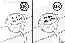
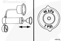
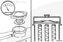
A commonly overlooked item when troubleshooting the cooling system is the radiator pressure/expansion tank cap. The cooling system is designed to use a pressure cap to prevent boiling of the coolant. An incorrect, damaged, or malfunctioning cap can result in the loss of coolant and in an engine overheating condition.
For information for pressure cap specifications, refer to the OEM service manual.
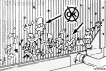
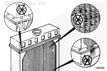
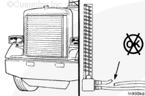
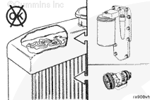
Air forced through the fins of the radiator by a fan cools the coolant pumped through the radiator. Environmental debris (such as paper, straw, lint, and dust) can obstruct the fins and reduce the flow of air, which will reduce the cooling effect of the radiator.
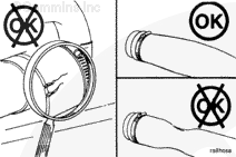
NOTE: The silicone engine coolant hose will exhibit swelling due to the elasticity of the hose.
Coolant Hoses
Collapsed or damaged coolant hoses can result in engine heating problems. Make sure to inspect all hoses for cracks, cuts, or collapsing. Replace any damaged hoses.
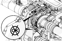
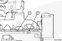
Inspect the coolant vent lines from the EGR cooler, cylinder head and variable geometry actuator (VGT). Make sure the lines are not pinched and that there are no sharp turns or dips in the vent lines from the engine connection point to the surge tank.
Blow shop air through the suspected lines to make sure there is no excessive restriction inside the lines.
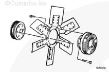
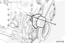
The engine cooling fan is typically driven by a crankshaft driven belt. In some applications, the fan is located off the engine for a remote mounted cooling system.
The cooling fan is supplied by the OEM. The OEM must be contacted for any service-related information. This procedure only highlights some of the items related to cooling fans.
If the fan is belt-driven, a slipping belt will result in a slower fan speed and reduced cooling. A malfunctioning automatic belt tensioner can be the problem. Refer to Procedure 008-080 in Section 8.
Check the bearings in the fan hub and other pulleys to make sure they are not causing excessive belt vibration and slippage. Refer to Procedure 008-036 in Section 8.
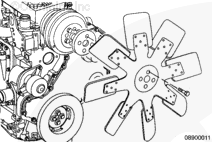
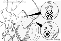
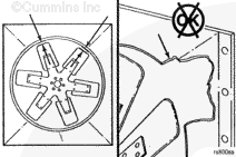
Do not straighten a bent fan blade or continue to use a damaged fan. A bent or damaged fan blade can fail during operation and cause personal injury or property damage.
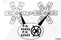
Only replace a damaged cooling fan with an exact equivalent cooling fan. Although same size cooling fans can appear similar, there can be differences in the blade pitch and profile.
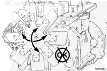
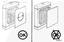
A fan shroud assembly is used to direct air flow provided by the cooling fan. A missing or damaged fan shroud will reduce the amount of air flow provided by the cooling fan and can cause an engine coolant overheating condition.
NOTE: Make sure the air temperature sensor is functioning correctly. Check the air-operated shutter controls. Check for air leaks. Refer to the OEM service manual.
Radiator shutters are designed to control airflow across the radiator. If the shutters fail to open when needed, the engine can run hot. Inability of the shutters to close can result in too much airflow and the engine running cold.
Winter fronts can be used to reduce the engine warm up time and help maintain engine heat in cold climate locations.
The winter fronts should only cover part of the frontal area of the cooling system, leaving part of the frontal area open to air flow.
Failure to leave part of the front area open to air flow or leaving the winter fronts installed when ambient temperatures increase can lead to an engine overheating condition.
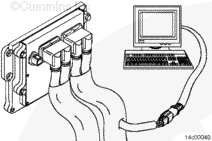
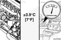
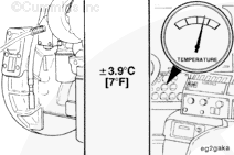
If equipped with an in dash coolant temperature gauge, monitor coolant temperature with an electronic service tool and compare the cab temperature gauge reading. Replace the cab temperature gauge if it is not within the manufacturer’s specifications of the correct reading.
If the manufacturer’s specifications are not available, replace the gauge if it is not within ±3.9°C or ±7°F of the correct reading.
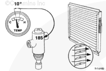
For vehicles equipped with temperature controlled shutters, check the coolant temperature at which the shutters open and close. Compare this value to what is stamped on the shutter control.
Cummins Inc. recommends that the shutters open at 85°C [185°F] engine coolant temperature.
If equipped with a temperature controlled cooling fan clutch, check the coolant temperature at which the fan clutch engages.
If the fan clutch engagement is controlled by a fan control on the vehicle, compare the recorded value to what is stamped on the fan control and/or reference the OEM service manual.
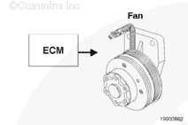
If the fan clutch engagement is controlled by the engine’s electronic control module (ECM), the engagement coolant temperature is a set value that can not be changed. If the fan clutch does not engage, check to make sure the fan control logic parameter is set correctly.
The ECM is capable of using either a zero (“0”) VDC or 12 VDC signal to engage the fan clutch. The exact enable logic can be selected in the Features and Parameters section of INSITE™ electronic service tool.
Cummins Inc. recommends that the fan engage at 96°C [205°F] engine coolant temperature.
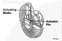
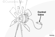
If equipped with a viscous fan drive, check the coolant temperature at which the fan engages. Viscous fan clutches are typically activated by a built-in sensor behind the radiator that monitors air temperature.
NOTE: Some viscous fan drives could possibly be electronically controlled.
When the air temperature reaches a specific level, depending on the temperature setting of the sensor used, the temperature-sensing control moves an actuator that allows viscous fluid to engage the fan drive and increase the fan speed. For more information, refer to the OEM service manual.
Cummins Inc. recommends that the fan engage at 96°C [205°F] engine coolant temperature.
The operating pressure of the coolant system and the lubricating system can result in the mixing of the fluids if there is a leak between the systems:
Cylinder head gasket
Lubricating oil cooler, etc.
Transmission/power steering/hydraulic fluid can also leak into the coolant through radiator fluid coolers, if equipped. Refer to the OEM service manual.
The Coolant Dam™/Pressure Tester service tool, Part Number 3824319, can also be used to pressurize the cooling system. The Coolant Dam™/Pressure Tester uses shop air rather than a hand air pump.
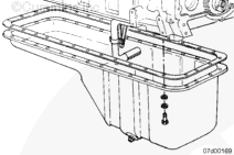
For internal coolant leaks, inspect the interior of the engine. It may be necessary to remove the following components to look for signs of a coolant leak:
For suspected fuel in the coolant or coolant in the fuel, disconnect the fuel drain connection at the rear of the cylinder head. Refer to Procedure 006-013 in Section 6.
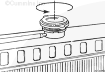
Do not remove the pressure cap from a hot engine. Wait until the coolant temperature is below 50°C [120°F] before removing the pressure cap. Heated coolant spray or steam can cause personal injury.
NOTE: All cab heaters and air conditioners must be turned to the OFF position, and the engine fan control must be turned to the AUTOMATIC position, if applicable.
Remove the radiator cap, and leave it off for the following test.
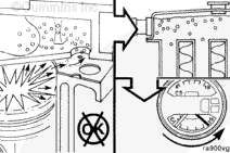
Monitor the sight glass installed on the service tool throughout the test. If air is observed, finish the test, and examine the combustion leak tester. This will determine the origin of the leak.
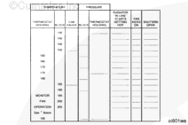
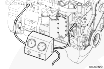
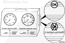
Temperature Readings:
There will be temperature fluctuations when switching the temperature selection valve. This fluctuation is normal and is caused by temperature loss in the line. The temperature will stabilize after a few seconds.
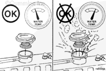
Air in the coolant can result in loss of coolant from the overflow when the aerated coolant is hot. The heated air expands, increasing the pressure in the system, causing the cap to open.
Similarly, coolant can be displaced through the overflow if the head gasket or a crack in the cylinder head leaks compression gases into the cooling system.
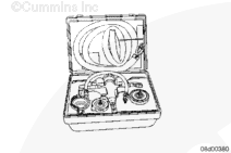
Use a combustion gas tester, Part Number 3822985, or its equivalent, to test for combustion gases in the cooling system.
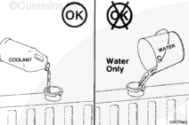
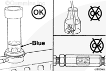
It is recommended that the cooling system contain a mixture of 50 percent antifreeze and 50 percent water during the combustion gas leak test. The use of water only can result in a color change in the test fluid from blue to turquoise or light green during the test. This is not an indication of a combustion gas leak.
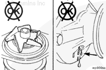
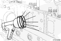
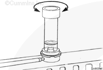
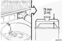
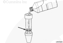
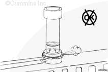
Insert the rubber tip of the combustion gas leak test instrument into the radiator fill neck. Hold the instrument down firmly and turn back and forth to make certain that an airtight seal is formed between the tester and the radiator fill neck.
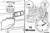
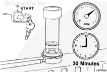
Start the engine and run at idle for approximately 30 minutes. Monitor the engine temperature and color of the test fluid during engine operation. Do not allow the engine temperature to exceed 100°C [212°F] during the test.
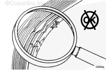
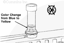
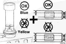
If the color of the test fluid changes from blue to yellow or green anytime during the test, combustion gases are leaking into the cooling system. Discontinue the test if the color of the test fluid changes from blue to yellow or green.
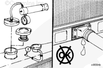
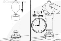
Insert the tip of the rubber ball into the hole in the top of the test instrument. Squeeze the rubber ball 2 to 3 minutes to draw air from the radiator through the test fluid.
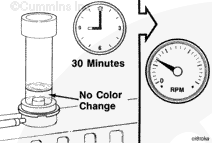
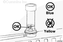
If the color of the test fluid remains blue, combustion gases are not entering the cooling system. If the color of the test fluid changes from blue to yellow or green, combustion gases are entering the cooling system and further investigation is required to determine the source of the combustion leak.
As the cooling system warms up to operating temperature, air will be expelled through the combustion gas tester in the form of bubbles in the test fluid. This is due to normal expansion of the coolant. Do not mistake the presence of air bubbles in the tester as combustion gases or air leaks into the cooling system. A change in the color of the test fluid from blue to yellow or green is the only indication of combustion gas in the cooling system.
Do not remove the pressure cap from a hot engine. Wait until the coolant temperature is below 50°C [120°F] before removing the pressure cap. Heated coolant spray or steam can cause personal injury.
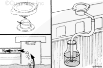
Allow the engine to cool and remove the radiator cap.
Operate the engine at rated rpm until it reaches a temperature of 82°C [180°F].
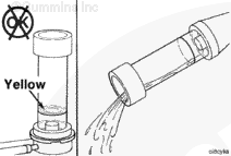
Check for a continuous flow of air bubbles from the hose in the water container.
NOTE: The engine coolant temperature must be stable to perform this test. An increasing coolant temperature will give a false indication of air due to expansion of the coolant in the system.
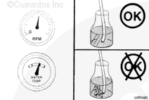
Check the color of fluid in the combustion gas leak tester. A yellow or green (not shown in the illustration) color will indicate a combustion leak. A blue color will indicate there is no leak. This information will help isolate the source of air in the cooling system, if any.
NOTE: The test kit is not sensitive enough to detect very small combustion gas leaks.
Do not rule out combustion gas leaks if the combustion gas leak test does not indicate a combustion gas leak.
Check the recorded coolant temperature when the shutters are opened. Compare this value to the stamp on the shutter control. Cummins Inc. recommends that the shutters open at 85°C [185°F].
Compare the cab temperature gauge reading with the block temperature. Replace the cab temperature gauge if it is not within the manufacturer’s specifications for the correct reading. If no manufacturer’s specifications are available, replace the gauge if it is not within ±3.9°C [7°F] of the correct reading.
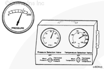
Read the recorded block pressure at 60°C [140°F]. If the block pressure is less than 138 kPa [20 psi] at high idle and without a pressure cap, check the following:
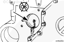
Remove the water pump
Inspect the impeller’s integrity, and for slippage on the shaft
Fill in the blanks with the test data as the test is being run. Mark when the radiator line gets hot, when the fan starts operating, and when the shutters open.
Hello, I'm Jack, a diesel engine fan and a blogger. I write about how to fix and improve diesel engines, from cars to trucks to generators. I also review the newest models and innovations in the diesel market. If you are interested in learning more about diesel engines, check out my blog and leave your feedback.
View all posts by Jack

 CAUTION
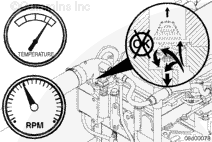


 WARNING
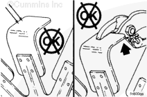


;)
;)
;)
;)
;)
;)
;)
;)
;)
;)
;)
;)
;)
;)
;)
;)
;)
;)
;)
;)
;)
;)
;)
;)
;)
;)
;)
;)
;)
;)
;)
;)
;)
;)
;)
;)
;)
;)
;)
;)
;)
;)
;)
;)
;)
;)
;)
;)
;)
;)
;)
;)
;)
;)
;)
;)
;)
;)
;)
;)
;)
;)
;)
;)
;)
;)
;)
;)
;)
;)
;)
;)
;)
;)
;)
;)
;)
;)
;)
;)
;)
;)
;)
;)
;)
;)
;)
;)
;)
;)
;)
;)
;)
;)
;)
;)
;)
;)
;)
;)
;)
;)
;)
;)
;)
;)
;)
;)
;)
;)
;)
;)
;)
;)
;)
;)
;)
;)