Engine Performance Troubleshooting Tree

Symptoms
- Engine Acceleration or Response Poor
- Cranking Fuel Pressure is Low
- Engine Operating Fuel Pressure is Low
- Engine Decelerates Slowly
- Engine Difficult to Start or Will Not Start (Exhaust Smoke)
- Engine Difficult to Start or Will Not Start (No Exhaust Smoke)
- Engine Power Output Low
- Engine Runs Rough at Idle
- Engine Runs Rough or Misfires
- Engine Speed Surges at Low or High Idle
- Engine Speed Surges Under Load or in Operating Range
- Engine Shuts Off or Dies Unexpectedly or Dies During Deceleration
- Engine Starts but Will Not Keep Running
- Engine Will Not Reach Rated Speed (RPM)
- Intake Manifold Pressure (Boost) is Below Normal
This troubleshooting procedure
must be followed for the following symptoms:
How To Use This Tree
This symptom tree can be used to troubleshoot all performance based symptoms listed above. Start by performing Step 1 troubleshooting. Step 2 will ask a series of questions and will provide a list of troubleshooting steps to perform depending on the symptom. Perform the list of troubleshooting in the sequence shown in the Specifications/Repair section of the tree.
Shop Talk
Driveability is a term that in general describes vehicle performance on the road. Driveability problems for an engine can be caused by several different factors. Some of the factors are engine-related and some are
not. Before troubleshooting it is important to determine the exact complaint and whether the engine has a real driveability problem or if it simply does
not meet driver expectations.
Low power is a term that is used in the field to describe many different performance problems. Low power is defined as the inability of the engine to produce the power necessary to move the vehicle at a speed that can be reasonably expected under the given conditions of load, grade, wind, and so on.
Poor acceleration or response is described as the inability of the vehicle to accelerate satisfactorily from a stop or from the bottom of a grade. It can also be the lag in acceleration during an attempt to pass or overtake another vehicle at conditions less than rated speed and load. Poor acceleration or response is difficult to troubleshoot since it can be caused by several factors.
Troubleshooting Steps
| STEPS | SPECIFICATIONS | |
|---|---|---|
| STEP 1. | Perform basic troubleshooting procedures. | |
| STEP 1A. Check for active fault codes or high counts of inactive fault codes. | Active fault codes or high counts of inactive fault codes? | |
| STEP 1B. Perform basic troubleshooting checks. | All steps have been verified to be correct? | |
| STEP 2. | Determination of engine symptom. | |
| STEP 2A. Low power, poor acceleration, or poor response. | Is the engine symptom low power, poor acceleration, or poor response? | |
| STEP 2B. Engine misfire, engine speed surge, or engine speed unstable. | Is the engine symptom engine misfire, engine speed surge, or engine speed unstable? | |
| STEP 2C. Low intake manifold pressure. | Is the engine symptom Low Boost Pressure? | |
| STEP 2D. Engine will not start or difficult to start, engine shuts off unexpectedly. | Is the symptom Engine Will Not Start or Difficult to Start, Engine Shuts Off Unexpectedly? | |
| STEP 3. | No-start troubleshooting procedures. | |
| STEP 3A. Check the engine speed during cranking. | Is the engine cranking speed greater than 150 rpm? | |
| STEP 3B. Check the ECM switched voltage at the ECM. | Is the switched voltage equal to the battery voltage? | |
| STEP 3B-1. Check the ECM key switch voltage at the 31 pin connector. | ||
| STEP 3C. Check the ECM unswitched battery supply voltage. | Is the ECM battery SUPPLY voltage equal to the battery voltage? | |
| STEP 3C-1. Check the ECM unswitched voltage at the 23 pin connector. | ||
| STEP 3D. Check for secondary fuel pressure while cranking the engine. | Is pressure correct for the platform? | |
| STEP 3D-1. Check primary fuel pressure while cranking the engine. | ||
| STEP 3E. Check fuel control valve while cranking the engine. | Was the gas mass flow compensation measured by INSITE™ electronic service tool greater than plus or minus 90 percent? | |
| STEP 3F. Check the ECM for Sync Counts. | Are the sync counts greater than 7 and increasing? | |
| STEP 3G. Check the ignition coils. | Was a bad coil found on cylinders 3 and 4? | |
| STEP 3H. Check the spark plugs. | Were all spark plugs found to be failed? | |
| STEP 3I. Check for other fault codes that explain a no-start condition. | Do any fault codes that can cause a no-start condition come active during cranking? | |
| STEP 4. | Fuel system troubleshooting procedures. | |
| STEP 4A. Check for secondary fuel pressure while cranking the engine. | Is pressure correct for the platform? | |
| STEP 4A-1. Check primary fuel pressure while cranking the engine. | ||
| STEP 4B. Check fuel system for oil contamination. | Was the amount of oil greater than 28.3 grams [1 oz] or were there signs of oil contamination on the gas mass flow sensor? | |
| STEP 4C. Check fuel mixer for damage or debris. | Were cracks or debris found in the mixer sleeve? | |
| STEP 4D. Verify secondary fuel pressure sensor accuracy. | Is the Fuel Pressure-Secondary (INSITE™ electronic service tool) value within 14 kPa [2 psi]? | |
| STEP 4E. Verify primary fuel pressure sensor accuracy. | Is the Fuel Pressure-Primary (INSITE™ electronic service tool) value within 14 kPa [2 psi]? | |
| STEP 4F. Check the fuel control valve. | Did the fuel control valve compensation vary more than 3 percent. | |
| STEP 4G. Move on to the next system for low power, poor acceleration, or poor response. | Is the engine symptom low power, poor acceleration, or poor response? | |
| STEP 4G-1. Move on to the next system for engine misfire, engine speed surge, or engine speed unstable. | ||
| STEP 5. | Air handling troubleshooting procedures. | |
| STEP 5A. Inspect the turbocharger blades for damage. | Damage found on turbocharger blades? | |
| STEP 5B. Check the turbocharger axial and radial clearances. | Are the turbocharger axial and radial bearing clearances within specification? | |
| STEP 5C. Determination of turbocharger type. | Is the turbocharger a variable geometry turbocharger? | |
| STEP 5D. Check variable geometry actuator rod for correct travel. | Does the turbocharger actuator rod extend between 10.8 and 11.8 mm [0.42 and 0.46 in]? | |
| STEP 5D-1. Check for air leaks and inspect air lines. | ||
| STEP 5D-2. Check for air pressure at the turbocharger control valve outlet. | ||
| STEP 5D-3. Check for air pressure at turbocharger control valve outlet. | ||
| STEP 5D-4. Check for vehicle air tank pressure at turbocharger control valve inlet. | ||
| STEP 5D-5. Check for correct turbocharger actuator travel. | ||
| STEP 5E. Check for broken shaft inside the turbocharger. | Does the sliding nozzle move correctly? | |
| STEP 5F. Inspect wastegate actuator hose or line. | Were holes or cracks found in the wastegate actuator hose? | |
| STEP 5G. Inspect wastegate control valve. | Does the air flow go into intake? | |
| STEP 5H. Inspect wastegate control valve vent to the atmosphere. | Does the air go to the atmosphere when +12 VDC is applied? | |
| STEP 5I. Inspect wastegate actuator rod for travel. | Does the wastegate actuator rod move? Note: All air handling Modes have been eliminated. | |
| STEP 5I-1. Inspect the wastegate actuator rod for travel. | ||
| STEP 5J. Move on to the next system for low power, poor acceleration, or poor response. | Is the engine symptom low power, poor acceleration, or poor response? | |
| STEP 5J-1. Move on to the next system for engine misfire, engine speed surge, or engine speed unstable. | ||
| STEP 6. | Electronic feature troubleshooting procedures. | |
| STEP 6A. Verify accelerator pedal travel. | Does the accelerator position read 0 when the accelerator is released and 100 percent when the accelerator is depressed? | |
| STEP 6B. Verify electronic feature settings are correct. | Are the electronic features set correctly? | |
| STEP 6C. Check the sensor voltage supplies. | Is the supply voltage 4.0 to 5.0 VDC? | |
| STEP 6C-1. Check the ECM unswitched voltage at the 23 pin connector. | ||
| STEP 6D. Check the ECM switched voltage at the ECM. | Is the switched voltage equal to the battery voltage? | |
| STEP 6D-1. Check the ECM key switch voltage at the 31 pin connector. | ||
| STEP 6E. Check the mixer inlet pressure sensor accuracy. | Is the intake mixer inlet pressure reading barometric pressure? | |
| STEP 6F. Check manifold absolute pressure sensor accuracy. | Is the manifold absolute pressure reading barometric pressure? | |
| STEP 6G. Compare manifold absolute pressure sensor to mixer inlet pressure. | Are the two pressure readings within 7 kPa [1 psi]? | |
| STEP 6G-1. Compare manifold absolute pressure sensor to gauge pressure. | ||
| STEP 6H. Check throttle actuator for proper operation. | Did the gas throttle control pass the test? | |
| STEP 6I. Determination of humidity sensor. | Does the engine have a humidity sensor? | |
| STEP 6I-1. Check humidity sensor accuracy. | ||
| STEP 6J. Move on to the next system for low power, poor acceleration, or poor response. | Is the engine symptom low power, poor acceleration, or poor response? | |
| STEP 7. | Base engine troubleshooting procedures. | |
| STEP 7A. Verify overhead adjustments are correct. | Are the overhead settings within the reset limits? | |
| STEP 7B. Inspect charge air cooler. | Is the charger air cooler free of cracks or damage? | |
| STEP 7C. Check air intake restriction. | Is air intake restriction greater than 635 mm H 2O [25 in H 2O]? |
|
| STEP 7D. Check exhaust restriction. | Exhaust back pressure within 61 to 127 mm-Hg [2.4 to 5.0 in-Hg]? | |
| STEP 7E. Check engine cylinder leakage. | Are the engine differential pressure measurements greater than 60 percent? | |
| STEP 7F. Check engine blowby. | Are the engine blowby measurements within specification? | |
| STEP 7F-1. Verify turbocharger contribution to engine blowby. | ||
| STEP 7G. Consult the next support level. | Have all steps been completed for the symptom? | |
| STEP 8. | Ignition System troubleshooting procedures. | |
| STEP 8A. Inspect the spark plugs. | Were any spark plugs found to be failed? | |
| STEP 8B. Determination of coil type. | Are they coil on plug type? | |
| STEP 8B-1. Inspect the coil boots. | ||
| STEP 8B-2. Inspect the plug wires. | ||
| STEP 8C. Check the ignition control module (ICM) power supply. | Is the ICM power SUPPLY equal to the battery voltage? | |
| STEP 8D. Check ICM resistance. | Is the resistance check within specifications? | |
| STEP 8E. Check ignition coils. | Was a bad coil found? | |
| STEP 8F. Move on to the next system for low power, poor acceleration, or poor response. | Is the engine symptom low power, poor acceleration, or poor response? | |
| STEP 9. | Open Loop troubleshooting procedures. | |
| STEP 9A. Operate the engine in Open Loop. | Did the vehicle performance change? | |
| STEP 9B. Check the sensor voltage supply 3. | Is the supply voltage +12.5 to 15.0 VDC? | |
| STEP 9B-1. Check the ECM unswitched voltage at the 23 pin connector. | ||
| STEP 9C. Verify oxygen sensor operation. | Did the sensor pass the test? | |
| STEP 9D. Verify oil consumption rate. | Is the oil consumption high? | |
| STEP 9E. Verify overhead adjustments are correct. | Are the overhead settings within the reset limits? | |
| STEP 9F. Check the gas mass flow sensor compensation. | Is the gas mass flow compensation reading greater than ± 25 percent? | |
Guided Step 1 – Perform basic troubleshooting procedures.
| Guided Step 1A – Check for active fault codes or high counts of inactive fault codes. | |
|---|---|
Conditions
ActionCheck for active fault codes.
|
|
|
Active fault codes or high counts of inactive fault codes? |
|
| YES | NO |
|
Follow the electronic fault code trees for the appropriate troubleshooting procedures. |
No Repair |
|
Repair complete
|
|
| Guided Step 1B – Perform basic troubleshooting checks. | |
|---|---|
ConditionsNone. ActionThe following items must be checked or verified before continuing:
|
|
|
All steps have been verified to be correct? |
|
| YES | NO |
| No Repair |
Correct the failure and verify complaint is no longer present after repair. |
|
Repair complete
|
|
Guided Step 2 – Determination of engine symptoms.
| Guided Step 2A – Low power, poor acceleration, or poor response. | |
|---|---|
ConditionsNone. ActionInterview driver and verify the complaint.
|
|
|
Is the engine symptom low power, poor acceleration, or poor response? |
|
| YES | NO |
|
Perform the troubleshooting steps in the recommended order listed below:
|
No Repair |
|
Perform the troubleshooting steps suggested in the repair procedure
|
|
| Guided Step 2B – Engine misfire, engine speed surge, or engine speed unstable. | |
|---|---|
ConditionsNone. ActionInterview driver and verify the complaint.
|
|
|
Is the engine symptom engine misfire, engine speed surge, or engine speed unstable? |
|
| YES | NO |
|
Perform the troubleshooting steps in the recommended order listed below:
|
No Repair |
|
Perform the troubleshooting steps suggested in the repair procedure.
|
|
| Guided Step 2C – Low intake manifold pressure. | |
|---|---|
ConditionsNone. ActionInterview driver and verify the complaint.
|
|
|
Is the engine symptom Low Boost Pressure? |
|
| YES | NO |
|
Perform the troubleshooting steps in the recommended order listed below:
|
No Repair |
|
Perform the troubleshooting steps suggested in the repair procedure
|
|
| Guided Step 2D – Engine will not start or difficult to start, engine shuts off unexpectedly. | |
|---|---|
ConditionsNone. ActionInterview driver and verify the complaint.
|
|
|
Is the symptom Engine Will |
|
| YES | NO |
|
Perform the troubleshooting steps in the recommended order listed below:
|
No Repair |
|
Perform the troubleshooting steps suggested in the repair procedure
|
Return to correct symptom tree.
|
Guided Step 3 – No-start troubleshooting procedures.
| Guided Step 3A – Check engine speed during cranking. | |
|---|---|
Conditions
ActionCrank the engine and monitor engine speed using electronic service tool.
|
|
|
Is the engine cranking speed greater than 150 rpm? |
|
| YES | NO |
| No Repair |
Find and correct the cause of low cranking speed. Check the batteries, engine starting motor, and accessory loads. Consult the Engine Will |
|
Repair complete
|
|
| Guided Step 3B – Check the ECM switched voltage at the ECM. | |
|---|---|
Conditions
ActionMeasure the voltage on the switched input SIGNAL wires of the ECM connector 2 to the engine block ground. Note: Measure the key switch voltage with the key switch in the “ON” position and also with the key switch in the “Cranking” position.
|
|
|
Is the switched voltage equal to the battery voltage? |
|
| YES | NO |
| No Repair | No Repair |
| Guided Step 3B-1 – Check the ECM key switch voltage at the 31 pin connector. | |
|---|---|
Conditions
ActionMeasure the voltage on the switched input SIGNAL wires on the 31 pin connector to the engine block ground. Note: Measure the key switch voltage with the key switch in the “ON” position and also with the key switch in the “Cranking” position.
|
|
|
Is the switched voltage equal to the battery voltage? |
|
| YES | NO |
|
Repair or replace the harness between the 50 pin connector and 31 pin connector. Refer to Procedure |
Repair or replace the OEM power harness fuses, key switch, or check the battery connections. |
|
Repair complete.
|
Repair complete.
|
| Guided Step 3C – Check the ECM unswitched battery supply voltage. | |
|---|---|
Conditions
ActionMeasure the voltage from the ECM battery SUPPLY (-) negative to the ECM battery SUPPLY (+) positive pins of the 50 pin ECM connector 1. Note: Measure the ECM Voltage with the keyswitch in the “On” position and also with the keyswitch in the “Cranking”” position.
|
|
|
Is the ECM battery SUPPLY voltage equal to the battery voltage? |
|
| YES | NO |
| No Repair | No Repair |
| Guided Step 3C-1 – Check the unswitched voltage at the 23 pin connector. | |
|---|---|
Conditions
ActionMeasure the voltage on the unswitched input SIGNAL wires of the 23 pin connector to the engine block ground. Note: Measure the ECM Voltage with the keyswitch in the “On” position and also with the keyswitch in the “Cranking”” position.
|
|
|
Is the unswitched voltage equal to the battery voltage? |
|
| YES | NO |
|
Repair or replace the harness between the 50 pin connector and the 23 pin connector. Refer to Procedure |
Repair or replace the OEM power harness, fuses, keyswitch, or check the battery connections. |
|
Repair complete.
|
Repair complete
|
| Guided Step 3D – Check for secondary fuel pressure while cranking the engine. | |
|---|---|
Conditions
ActionMeasure the fuel pressure while cranking the engine.
Note: All pressure sensors on the Gas Plus engines are absolute pressure sensors. The minimum values are: B Gas Plus – 414 kPa [60 psia] B LPG Plus – 276 kPa [40 psia] C Gas Plus – 517 kPa [75 psia] Note: Attempting to start the engine will assure the fuel shut off valve remains open. |
|
|
Is pressure correct for the platform? |
|
| YES | NO |
| No Repair | No Repair |
| Guided Step 3D-1 – Check the primary fuel pressure while cranking the engine. | |
|---|---|
Conditions
ActionCheck the primary fuel pressure.
Note: Attempting to start the engine will assure the fuel shut off valve remains open. Note: All pressure sensors on the Gas Plus engines are absolute pressure sensors. The minimum values are: B Gas Plus – 414 kPa [60 psia] B LPG Plus – 276 kPa [40 psia] C Gas Plus – 517 kPa [75 psia] |
|
|
Is pressure correct for the platform? |
|
| YES | NO |
|
Replace the low pressure regulator. Refer to Procedure |
Refer to the OEM troubleshooting of the high pressure regulator, shut off valve and restricted fuel lines. |
|
Repair complete.
|
Repair complete.
|
| Guided Step 3E – Check fuel control valve while cranking the engine. | |
|---|---|
Conditions
ActionCrank the engine and use INSITE™ electronic service tool to monitor the gas mass flow compensation. Note: Attempting to start the engine will assure the fuel shut off valve remains open. |
|
|
Was the gas mass flow compensation measured by INSITE™ electronic service tool greater than plus or minus 90 percent? |
|
| YES | NO |
|
Replace the fuel control valve. Refer to Procedure |
No Repair |
|
Repair complete
|
|
| Guided Step 3F – Check ECM for Sync Counts. | |
|---|---|
Conditions
ActionAttempt to start the engine by engaging the engine starter for at least 30 continuous seconds.
|
|
|
Are the sync counts greater than 7 and increasing? |
|
| YES | NO |
|
Refer to Fault Code 753, Engine Position Sensor Synchronization Error. |
No Repair |
|
Repair complete.
|
|
| Guided Step 3G – Check Ignition Coils. | |
|---|---|
Conditions
ActionCheck ignition coils.
Note: A failure to the primary circuit on cylinders 3 or 4 will prevent all spark plugs from firing on engines with the three connector type ICM. |
|
|
Was a bad coil found on cylinders 3 and 4? |
|
| YES | NO |
|
Refer to Procedure |
No Repair |
|
Repair complete.
|
|
| Guided Step 3H – Check Spark Plugs. | |
|---|---|
Conditions
ActionCheck the spark plugs.
|
|
|
Were all spark plugs found to be failed? |
|
| YES | NO |
|
Refer to Procedure |
No Repair |
|
Repair complete
|
|
| Guided Step 3I – Check for other fault codes that explain a no-start condition. | |
|---|---|
Conditions
ActionUse INSITE™ electronic service tool to check for fault codes that explain no-start condition.
|
|
|
Do any fault codes that can cause a no-start condition come active during cranking? |
|
| YES | NO |
|
Follow the electronic fault code trees for the appropriate troubleshooting procedure. |
No Repair |
|
Repair complete.
|
|
Guided Step 4 – Fuel system troubleshooting procedures.
| Guided Step 4A – Check for secondary fuel pressure while cranking the engine. | |
|---|---|
Conditions
ActionMeasure the fuel pressure while cranking the engine.
Note: All pressure sensors on the Gas Plus engines are absolute pressure sensors. The minimum values are: B Gas Plus – 414 kPa [60 psia] B LPG Plus – 276 kPa [40 psia] C Gas Plus – 414 kPa [60 psia] L Gas Plus – 414 kPa [60 psia] Note: Attempting to start the engine will assure the fuel shut off valve remains open. |
|
|
Is pressure correct for the platform? |
|
| YES | NO |
| No Repair | No Repair |
| Guided Step 4A-1 – Check the primary fuel pressure while cranking the engine. | |
|---|---|
Conditions
ActionCheck the primary fuel pressure.
Note: Attempting to start the engine will assure the fuel shut off valve remains open. Note: All pressure sensors on the Gas Plus engines are absolute pressure sensors. The minimum values are: B Gas Plus – 414 kPa [60 psia] B LPG Plus – 276 kPa [40 psia] C Gas Plus – 414 kPa [60 psia] L Gas Plus – 414 kPa [60 psia] |
|
|
Is pressure correct for the platform? |
|
| YES | NO |
|
Replace the low pressure regulator. Refer to Procedure |
Refer to the OEM troubleshooting of the high pressure regulator, shut off valve and restricted fuel lines. |
|
Repair complete.
|
Repair complete.
|
| Guided Step 4B – Check fuel system for oil contamination. | |
|---|---|
ConditionsActionCheck for oil in the fuel filter.
|
|
|
Was the amount of oil greater than 28.3 grams [1 oz] or were there signs of oil contamination on the gas mass flow sensor? |
|
| YES | NO |
|
Clean the fuel system beginning at the low pressure regulator. Refer to Procedure |
No Repair |
|
Repair complete
|
|
| Guided Step 4C – Check the fuel mixer for damage or debris. | |
|---|---|
ConditionsActionCheck fuel mixer for damage or debris.
|
|
|
Were cracks or debris found in the mixer sleeve? |
|
| YES | NO |
| No Repair | |
|
Repair complete.
|
|
| Guided Step 4D – Verify secondary fuel pressure sensor accuracy. | |
|---|---|
Conditions
ActionCheck secondary fuel pressure sensor accuracy.
|
|
|
Is the Fuel Pressure-Secondary (INSITE™ electronic service tool) value within 14 kPa [2 psi]? |
|
| YES | NO |
| No Repair |
Replace the fuel pressure sensor. Refer to Procedure |
|
Repair complete.
|
|
| Guided Step 4E – Verify the primary fuel pressure sensor accuracy. | |
|---|---|
Conditions
ActionVerify primary fuel pressure sensor accuracy.
|
|
|
Is the Fuel Pressure-Primary (INSITE™ electronic service tool) value within 14 kPa [2 psi]? |
|
| YES | NO |
| No Repair |
Replace the fuel pressure sensor. Refer to Procedure . |
|
Repair complete.
|
|
| Guided Step 4F – Check Fuel Control Valve. | |
|---|---|
Conditions
|
|
|
Did the fuel control valve compensation vary more than 3 percent? |
|
| YES | NO |
|
Replace the fuel control valve. Refer to Procedure |
Note: All Fuel system Modes have been eliminated. |
|
Repair complete.
|
|
| Guided Step 4G – Move on to the next system for low power, poor acceleration, or poor response. | |
|---|---|
Conditions
ActionMove onto next system.
|
|
|
Is the engine symptom low power, poor acceleration, or poor response? |
|
| YES | NO |
| No Repair | No Repair |
| Guided Step 4G-1 – Move on to the next system for engine misfire, engine speed surge, or engine speed unstable. | |
|---|---|
Conditions
ActionMove onto next system.
|
|
|
Is the engine symptom engine misfire, engine speed surge, or engine speed unstable? |
|
| YES | NO |
| No Repair | No Repair |
Guided Step 5 – Air handling troubleshooting procedures.
| Guided Step 5A – Inspect the turbocharger blades for damage. | |
|---|---|
Conditions
ActionInspect the compressor and turbine blades for damage or wear. |
|
|
Damage found on turbocharger blades? |
|
| YES | NO |
|
Replace the turbocharger assembly. Refer to Procedure |
No Repair |
|
Repair complete
|
|
| Guided Step 5B – Check the turbocharger axial and radial clearances. | |
|---|---|
Conditions
ActionCheck the turbocharger for correct axial and radial clearance. |
|
|
Are the turbocharger axial and radial bearing clearances within specification? |
|
| YES | NO |
| No Repair |
Replace the turbocharger assembly. Refer to Procedure |
|
Repair complete
|
|
| Guided Step 5C – Determination of turbocharger type. | |
|---|---|
ConditionsNone ActionDetermine if the turbocharger is a wastegated or variable geometry turbocharger.
|
|
|
Is the turbocharger a variable geometry turbocharger? |
|
| YES | NO |
| No Repair | No Repair |
| Guided Step 5D – Check variable geometry actuator rod for correct travel. | ||
|---|---|---|
Conditions
ActionUse INSITE™ electronic service tool to start the Turbocharger Actuator Test
Note: The variable geometry actuator |
|
|
|
Does the turbocharger actuator rod extend between 10.8 and 11.8 mm [0.42 and 0.46 in]? |
||
| YES | NO | |
| No Repair | No Repair | |
| Guided Step 5D-1 – Check for air leaks and inspect air lines. | |
|---|---|
Conditions
ActionUse INSITE™ electronic service tool to perform the Turbocharger Actuator Test. Select the Extended Actuator position and listen for air leaks in the following components:
Note: A small amount of air will be heard escaping from the turbocharger control valve. This is a normal condition. Do |
|
|
Air leaks found in the system or damaged air lines? |
|
| YES | NO |
|
Repair air leaks or replace damaged or broken air lines. |
No Repair |
|
Repair complete
|
|
| Guided Step 5D-2 – Check for air pressure at the turbocharger control valve outlet. | |
|---|---|
Conditions
ActionRemove the air line connection at the outlet of the turbocharger control valve.
|
|
|
Is vehicle tank air pressure present at the turbocharger control valve outlet? |
|
| YES | NO |
| No Repair | No Repair |
| Guided Step 5D-3 – Check for air pressure at turbocharger control valve outlet. | |
|---|---|
Conditions
ActionRemove the air line connection at the outlet of the turbocharger control valve.
|
|
|
Can air be heard escaping from the turbocharger control valve outlet? |
|
| YES | NO |
|
The turbocharger control valve is stuck open. It |
No Repair |
|
Repair complete
|
|
| Guided Step 5D-4 – Check for vehicle air tank pressure at turbocharger control valve inlet. | |
|---|---|
Conditions
ActionDisconnect the air inlet connection to the turbocharger control valve. Verify vehicle air tank pressure is available at the turbocharger control valve inlet. |
|
|
Vehicle air tank pressure available at the turbocharger control valve inlet? |
|
| YES | NO |
| No Repair |
No air pressure available at the turbocharger control valve inlet. Troubleshoot OEM air plumbing and determine why air pressure is |
|
Repair complete
|
|
| Guided Step 5D-5 – Check for correct turbocharger actuator travel. | ||
|---|---|---|
Conditions
ActionUse INSITE™ electronic service tool to perform the Turbocharger Actuator Test.
|
|
|
|
Does the variable geometry actuator rod travel at least 12 mm [0.472 in]? |
||
| YES | NO | |
|
The variable geometry actuator has correct air pressure and correct travel. The variable geometry mechanism in the turbocharger is seized. Replace the turbocharger assembly. Refer to Procedure |
The variable geometry actuator has correct air pressure but the variable geometry actuator rod is Replace the turbocharger actuator. Refer to Procedure |
|
|
Repair complete
|
Repair complete
|
|
| Guided Step 5E – Check for broken shaft inside the turbocharger. | ||
|---|---|---|
Conditions
ActionCheck for a broken linkage inside the turbocharger by moving the variable geometry actuator on the turbocharger up and down.
|
|
|
|
Does the sliding nozzle move correctly? |
||
| YES | NO | |
| No Repair |
The variable geometry has a mechanical failure inside the turbocharger. The actuator moves properly, but the linkage attaching the actuator to the nozzle is broken. Replace the turbocharger assembly. Refer to Procedure |
|
|
Repair complete
|
||
| Guided Step 5F – Inspect wastegate actuator hose/line. | |
|---|---|
Conditions
ActionInspect the integral wastegate actuator hose for cracks or holes.
|
|
|
Were holes or cracks found in the wastegate actuator hose? |
|
| YES | NO |
|
Replace the wastegate actuator hose. |
No Repair |
|
Repair complete
|
|
| Guided Step 5G – Inspect wastegate control valve. | |
|---|---|
Conditions
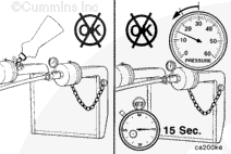
ActionApply a regulated air supply of 128 kPa [20 psi] to the wastegate control line connection.
|
|
|
Does the air flow go into intake? |
|
| YES | NO |
| No Repair |
Replace the wastegate control valve. Refer to Procedure |
|
Repair complete.
|
|
| Guided Step 5H – Inspect wastegate control valve vent to atmosphere. | |
|---|---|
Conditions
ActionApply a regulated air supply of 128 kPa [20 psi] to the wastegate control line connection.
|
|
|
Does the air go to the atmosphere when +12 VDC is applied? |
|
| YES | NO |
| No Repair |
Replace the wastegate control valve. Refer to Procedure |
|
Repair complete.
|
|
| Guided Step 5I – Inspect the wastegate actuator rod for travel. | ||
|---|---|---|
Conditions
ActionApply a regulated air supply of 128 kPa [20 psi] to the wastegate actuator.
|
|
|
|
Does the wastegate actuator rod move? Note: All air handling Modes have been eliminated. |
||
| YES | NO | |
| No Repair | No Repair | |
| Guided Step 5I-1 – Inspect the wastegate actuator rod for travel. | ||
|---|---|---|
Conditions
ActionApply a regulated air supply of 128 kPa [20 psi] to the wastegate actuator.
|
|
|
|
Does the wastegate actuator rod move? |
||
| YES | NO | |
|
Move the wastegate lever on the turbocharger back and forth and check for smooth operation. Replace the turbocharger assembly if the wastegate is seized. Refer to Procedure |
Replace the wastegate actuator. Refer to Procedure |
|
|
Repair complete.
|
Repair complete.
|
|
| Guided Step 5J – Move on to the next system for low power, poor acceleration, or poor response. | |
|---|---|
Conditions
ActionMove on to next system.
|
|
|
Is the engine symptom low power, poor acceleration, or poor response? |
|
| YES | NO |
| No Repair | No Repair |
| Guided Step 5J-1 – Move on to the next system for engine misfire, engine speed surge, or engine speed unstable. | |
|---|---|
Conditions
ActionMove onto next system.
|
|
|
Is the engine symptom engine misfire, engine speed surge, or engine speed unstable? |
|
| YES | NO |
| No Repair | No Repair |
Guided Step 6 – Electronic feature troubleshooting procedures.
| Guided Step 6A – Verify accelerator pedal travel. | |
|---|---|
Conditions
ActionUse INSITE™ electronic service tool to monitor Accelerator Position while fully depressing and releasing the accelerator pedal. Monitor Accelerator Position with INSITE™ electronic service tool while fully depressing and releasing the accelerator pedal. |
|
|
Does the accelerator position read 0 when the accelerator is released and 100 percent when the accelerator is depressed? |
|
| YES | NO |
| No Repair |
Determine and correct the cause of the accelerator pedal restriction. |
|
Repair complete
|
|
| Guided Step 6B – Verify electronic feature settings are correct. | |
|---|---|
Conditions
ActionWith INSITE™ electronic service tool verify the following adjustable parameters are correctly set.
|
|
|
Are the electronic features set correctly? |
|
| YES | NO |
| No Repair |
Use INSITE™ electronic service tool to correct the programmable features. |
|
Repair Complete
|
|
| Guided Step 6C – Check the sensor voltage supplies. | |
|---|---|
Conditions
ActionUse INSITE™ electronic service tool to monitor sensor supply voltage 1, 2 and 4. Use INSITE™ electronic service tool to monitor sensor supply voltage 1, 2 and 4. |
|
|
Is the supply voltage 4.0 to 5.0 VDC? |
|
| YES | NO |
| No Repair | No Repair |
| Guided Step 6C-1 – Check the ECM unswitched voltage at the 23 pin connector. | |
|---|---|
Conditions
ActionMeasure the voltage on the SIGNAL wires of the 23 pin connector to the engine block ground. Note: Measure the keyswitch voltage with the keyswitch in the “ON” position and also with the keyswitch in the “Cranking” position. Refer to the wiring diagram for connector pin identification. |
|
|
Is the unswitched voltage equal to the battery voltage? |
|
| YES | NO |
|
Repair or replace the harness between the 50 pin connector and the 23 pin connector. Refer to Procedure |
Repair or replace the OEM power harness, fuse, keyswitch, or check the battery connections. |
|
Repair complete.
|
Repair complete.
|
| Guided Step 6D – Check the ECM switched voltage at the ECM. | |
|---|---|
Conditions
ActionMeasure the voltage on the switched input SIGNAL wires of the ECM connector 2 to the engine block ground. Note: Measure the keyswitch voltage with the keyswitch in the “ON” position and also with the keyswitch in the “Cranking” position. Refer to the wiring diagram for connector pin identification. |
|
|
Is the switched voltage equal to the battery voltage? |
|
| YES | NO |
| No Repair | No Repair |
| Guided Step 6D-1 – Check the ECM keyswitch voltage at the 31 pin connector. | |
|---|---|
Conditions
ActionMeasure the voltage on the switched input SIGNAL wires of the 31 pin connector to the engine block ground. Note: Measure the keyswitch voltage with the keyswitch in the “ON” position and also with the keyswitch in the “Cranking” position. Refer to the wiring diagram for connector pin identification. |
|
|
Is the switched voltage equal to the battery voltage? |
|
| YES | NO |
|
Repair or replace the harness between the 50 pin connector and the 23 pin connector. Refer to Procedure |
Repair or replace the OEM power harness, fuse, keyswitch, or check the battery connections. |
|
Repair complete.
|
Repair complete.
|
| Guided Step 6E – Check mixer inlet pressure sensor accuracy. | |
|---|---|
Conditions
ActionUse INSITE™ electronic service tool to monitor the value of the mixer inlet pressure without the engine running. Note: The present barometric pressure in psi is determined by multiplying the local weather station barometric pressure in inches of mercury by 0.4911. |
|
|
Is the intake mixer inlet pressure reading barometric pressure? |
|
| YES | NO |
| No Repair |
Replace the mixer inlet pressure sensor. Refer to Procedure |
|
Repair complete.
|
|
| Guided Step 6F – Check manifold absolute pressure sensor accuracy. | |
|---|---|
Conditions
ActionUse INSITE™ electronic service tool to monitor the value of the manifold absolute pressure without the engine running. Note: The present barometric pressure in psi is determined by multiplying the local weather station barometric pressure in inches of mercury by 0.4911. |
|
|
Is the manifold absolute pressure reading barometric pressure? |
|
| YES | NO |
| No Repair |
Replace the manifold absolute pressure sensor. Refer to Procedure |
|
Repair complete.
|
|
| Guided Step 6G – Compare manifold absolute pressure sensor to mixer inlet pressure. | |
|---|---|
Conditions
ActionUse INSITE™ electronic service tool to monitor the values for the manifold absolute pressure and mixer inlet pressure.
|
|
|
Are the two pressure readings within 7 kPa [1 psi]? |
|
| YES | NO |
| No Repair | No Repair |
| Guided Step 6G-1 – Compare manifold absolute pressure sensor to gauge pressure. | |
|---|---|
Conditions
ActionUse INSITE™ electronic service tool to monitor the values for the manifold absolute pressure.
|
|
|
Are the two pressure readings within 7 kPa [1 psi]? |
|
| YES | NO |
|
Replace the mixer inlet pressure sensor. Refer to Procedure |
Replace the manifold absolute pressure sensor. Refer to Procedure |
|
Repair complete.
|
Repair complete.
|
| Guided Step 6H – Check throttle actuator for proper operation. | |
|---|---|
Conditions
ActionVerify proper throttle operation.
|
|
|
Did the gas throttle control pass the test? |
|
| YES | NO |
| No Repair |
Repair or replace the throttle actuator. Refer to Procedure |
|
Repair complete.
|
|
| Guided Step 6I – Determination of humidity sensor. | |
|---|---|
ConditionsNone ActionVerify the engine is equipped with a humidty sensor.
|
|
|
Does the engine have a humidity sensor? |
|
| YES | NO |
| No Repair | No Repair |
| Guided Step 6I-1 – Check humidity sensor accuracy. | ||
|---|---|---|
Conditions
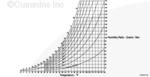
ActionUse INSITE™ electronic service tool to monitor the value of the humidity sensor. Use the psychrometric chart to determine the current grains/lb of humidity.
The default value of the humidity sensor is 75 grains/lb. |
|
|
|
Is the humidity sensor reading current absolute humidity within ±10 grains? |
||
| YES | NO | |
| No Repair |
Replace the humidity sensor. Refer to Procedure |
|
|
Repair complete.
|
||
| Guided Step 6J – Move on to the next system for low power, poor acceleration, or poor response. | |
|---|---|
Conditions
ActionMove on to next system.
|
|
|
Is the engine symptom low power, poor acceleration, or poor response? |
|
| YES | NO |
| No Repair | No Repair |
Guided Step 7 – Base engine troubleshooting procedures.
| Guided Step 7A – Verify overhead adjustments are correct. | |
|---|---|
Conditions
|
|
|
Are the overhead settings within the reset limits? |
|
| YES | NO |
| No Repair |
Adjust the overhead settings. Refer to Procedure |
|
Repair complete
|
|
| Guided Step 7B – Inspect the charge air cooler. | ||
|---|---|---|
ConditionsActionInspect the charge air cooler.
|
|
|
|
Is the charger air cooler free of cracks or damage? |
||
| YES | NO | |
| No Repair |
Repair or replace the charge air cooler. Refer to Procedure |
|
|
Repair complete
|
||
| Guided Step 7C – Check air intake restriction. | ||
|---|---|---|
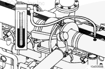
ConditionsActionCheck the intake system restriction.
|
|
|
|
Is air intake restriction greater than 635 mm H |
||
| YES | NO | |
|
Correct the cause of high intake air restriction. Check for plugged air filter or restricted air intake piping. Refer to Procedure |
No Repair | |
|
Repair complete
|
||
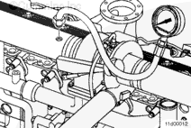
| Guided Step 7D – Check exhaust restriction. | ||
|---|---|---|
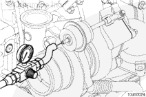
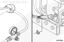
ConditionsActionCheck the exhaust system back pressure. Check the exhaust system back pressure by installing a pressure gauge into the exhaust system just past the turbocharger outlet. Refer to Procedure |
|
|
|
Exhaust back pressure within 61 to 127 mm-Hg [2.4 to 5.0in-Hg]? |
||
| YES | NO | |
| No Repair |
Inspect exhaust system for source of high restriction. Refer to Procedure |
|
|
Repair complete
|
||
;)
;)
;)
;)
;)
;)
;)
;)
;)
;)
;)
;)
;)
;)
;)
;)
;)
;)
| Guided Step 7E – Check engine cylinder leakage. | |
|---|---|
Conditions
ActionMeassure engine cylinder differential pressure.
|
|
|
Are the engine differential pressure measurements greater than 60 percent? |
|
| YES | NO |
| No Repair |
Remove the cylinder head and inspect valves, valve seats, piston rings, and cylinder condition for source of cylinder leakage. Refer to Procedures |
|
Repair complete.
|
|
| Guided Step 7F – Check engine blowby. | |
|---|---|
ConditionsActionMeasure the engine blowby. |
|
|
Are the engine blowby measurements within specification? |
|
| YES | NO |
| No Repair | No Repair |
| Guided Step 7F-1 – Verify turbocharger contribution to engine blowby. | |
|---|---|
Conditions
ActionLoad engine to rated rpm on a chassis dynamometer. |
|
|
Has the total engine blowby dropped more than 30 percent of the total? |
|
| YES | NO |
|
Replace the turbocharger assembly. Refer to Procedure |
Repair or replace the air compressor assembly. Refer to Procedure |
|
Repair complete
|
Repair complete
|
| Guided Step 7G – Move to the next support level. | |
|---|---|
ConditionsNone ActionReview all data collected to this point.
|
|
|
Have all steps been completed for the symptom? |
|
| YES | NO |
|
Move to the next level of support. |
Return to the steps |
|
Repair complete.
|
Repair complete.
|
Guided Step 8 – Ignition System troubleshooting procedures.
| Guided Step 8A – Inspect the spark plugs. | |
|---|---|
Conditions
ActionInspect the spark plugs.
|
|
|
Were any spark plugs found to be failed? |
|
| YES | NO |
|
Replace the spark plugs. Refer to Procedure |
No Repair |
|
Repair complete.
|
|
| Guided Step 8B – Determination of coil type. | |
|---|---|
ConditionsNone ActionDetermine which type of coils are installed.
|
|
|
Are they coil on plug type? |
|
| YES | NO |
| No Repair | No Repair |
| Guided Step 8B-1 – Inspect the coil boots. | |
|---|---|
Conditions
ActionInspect coil on plug boots.
|
|
|
Was damage found on the coil boot? |
|
| YES | NO |
|
Replace boots. Refer to Procedure |
No Repair |
|
Repair complete.
|
|
| Guided Step 8B-2 – Inspect spark plug wires. | |
|---|---|
Conditions
ActionInspect spark plug wires.
|
|
|
Was damage found on any spark plug wires? |
|
| YES | NO |
|
Replace the damaged spark plug wire(s). Refer to Procedure |
No Repair |
|
Repair complete.
|
|
| Guided Step 8C – Check the ICM power supply. | |
|---|---|
Conditions
ActionMeasure the switched battery voltage to the ICM.
Note: Measure the voltage with the keyswitch in the “ON” position and also with the keyswitch in the “Cranking” position. Refer to the wiring diagram for connector pin identification. |
|
|
Is the ICM power SUPPLY equal to the battery voltage? |
|
| YES | NO |
| No Repair | No Repair |
| Guided Step 8D – Check the ICM resistance. | |
|---|---|
Conditions
ActionMeasure the ICM resistance.
|
|
|
Is the resistance check within specifications? |
|
| YES | NO |
| No Repair |
Replace the ICM. Refer to Procedure |
|
Repair complete.
|
|
| Guided Step 8E – Check the ignition coils. | |
|---|---|
Conditions
ActionInspect the ignition coils.
Note: A failure to the primary circuit on cylinders 3 or 4 will prevent all the plugs from firing. |
|
|
Was a bad coil found? |
|
| YES | NO |
|
Replace the bad coil(s). Refer to Procedure |
No Repair |
|
Repair complete.
|
|
| Guided Step 8F – Move on to the next system for low power, poor acceleration, or poor response. | |
|---|---|
Conditions
ActionMove onto next system.
|
|
|
Is the engine symptom low power, poor acceleration, or poor response? |
|
| YES | NO |
| No Repair | No Repair |
Guided Step 9 – Open Loop troubleshooting procedure.
| Guided Step 9A – Operate the engine in Open Loop. | |
|---|---|
Conditions
ActionLock the engine in Open Loop.
|
|
|
Did the vehicle performance change? |
|
| YES | NO |
| No Repair | No Repair |
| Guided Step 9B – Check sensor voltage supply 3. | |
|---|---|
Conditions
ActionMonitor sensor voltage supply 3.
|
|
|
Is the supply voltage +12.5 to 15.0 VDC? |
|
| YES | NO |
| No Repair | No Repair |
| Guided Step 9B-1 – Check the ECM unswitched voltage at the 23 pin connector. | |
|---|---|
Conditions
ActionCheck the ECM unswitched voltage.
Note: Measure the keyswitch voltage with the keyswitch on the “ON” position and also with the keyswitch in the “Cranking” position. Refer to the wiring diagram for connector pin identification. |
|
|
Is the unswitched voltage equal to the battery voltage? |
|
| YES | NO |
|
Repair or replace the harness between the 50 pin connector and 23 pin connector. Refer to Procedure |
Repair or replace the OEM power harness, fuses, keyswitch, or check the battery connections. |
|
Repair complete.
|
Repair complete.
|
| Guided Step 9C – Verify oxygen sensor operation. | |
|---|---|
Conditions
ActionPerform the Heated Oxygen Sensor test using the INSITE™ Electronic Service Tool.
|
|
|
Did the sensor pass the test? |
|
| YES | NO |
| No Repair |
Replace the heated oxygen sensor. Refer to Procedure Use INSITE™ electronic service tool to reset the fuel tables. |
|
Repair complete
|
|
| Guided Step 9D – Verify oil consumption rate. | |
|---|---|
Conditions
ActionCheck oil consumption against mileage.
|
|
|
Is the oil consumption high? |
|
| YES | NO |
|
Follow the Lubricating Oil Consumption Excessive troubleshooting tree. |
No Repair |
|
Repair complete.
|
|
| Guided Step 9E – Verify overhead adjustments are correct. | |
|---|---|
Conditions
|
|
|
Are the overhead settings within the reset limits? |
|
| YES | NO |
| No Repair |
Adjust the overhead settings. Refer to Procedure |
|
Repair complete
|
|
| Guided Step 9F – Check the gas mass flow sensor compensation. | |
|---|---|
Conditions
ActionUse INSITE™ Electronic Service Tool to monitor the value of gas mass flow sensor compensation.
|
|
|
Is the gas mass flow compensation reading greater than ± 25 percent? |
|
| YES | NO |
|
Replace the gas mass flow sensor. Refer to Procedure |
Engine has an ignition related engine misfire. Follow steps in Step 8. |
|
Repair complete.
|
|