Do not remove the pressure cap from a hot engine. Wait until the coolant temperature is below 50°C [120°F] before removing the pressure cap. Heated coolant spray or steam can cause personal injury.
WARNING
Coolant is toxic. Keep away from children and pets. If not reused, dispose of in accordance with local environmental regulations.
NOTE: If the EGR cooler is being replaced due to an internal coolant leak, the EGR differential pressure tubes must be replaced.
NOTE: Brush away all loose dirt from around the area of the air handling connections to avoid contamination of the interior of the engine.
NOTE: If the Exhaust Gas Recirculation (EGR) cooler is being replaced due to an internal coolant leak, the EGR differential pressure tubes must be replaced.
NOTE: Brush away all loose dirt from around the area of the air-handling connections to avoid contamination of the interior of the engine.
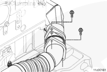
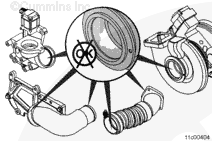
Remove the air intake pipe to turbocharger. Refer to the OEM service manual. Use protective caps from the Cummins® Vehicle Air Pumping Clean Care Kit, Part Number 4912425, to cover the connection points.
Remove the charge-air cooler pipe between the turbocharger and charge-air cooler. Refer to the OEM service manual. Use protective caps from the Cummins® Vehicle Plumbing Clean Care Kit, Part Number 4919425, to cover the connection points.
Do not remove the pressure cap from a hot engine. Wait until the coolant temperature is below 50°C [120°F] before removing the pressure cap. Heated coolant spray or steam can cause personal injury.
WARNING
Coolant is toxic. Keep away from children and pets. If not reused, dispose of in accordance with local environmental regulations.
NOTE: Brush away all loose dirt from around the area of the air handling connections to avoid contamination of the interior of the engine.
NOTE: If the EGR cooler is being replaced due to a malfunction that caused an internal coolant leak, the crankcase breather element must be replaced.
NOTE: If the EGR cooler is being replaced due to a malfunction that caused an internal coolant leak, the EGR differential pressure sensor tubes should be inspected for deposits. If deposits are found, replace the EGR differential pressure tubes.
NOTE: If pressure testing the EGR cooler on ISX CM871 engines, do not remove the aftertreatment injector or turbocharger before pressure testing the EGR cooler.
Remove the air intake pipe to turbocharger. Refer to the OEM service manual. Use protective caps from the Cummins® Vehicle Air Plumbing Clean Care Kit, Part Number 4919425, to cover the connection points.
Remove the charge-air cooler pipe between the turbocharger and charge-air cooler. Refer to the OEM service manual. Use protectve caps from the Cummins® Vehicle Plumbing Clean Care Kit, Part Number 4919425, to cover the connection points.
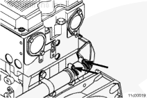
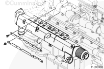
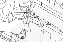
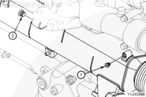
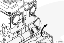
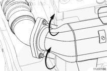
Loosen the v-band clamp between the EGR cooler and the exhaust manifold. In order to prevent damage to the EGR cooler bellows, place the v-band clamp over the exhaust manifold flange.
When using solvents, acids, or alkaline materials for cleaning, follow the manufacturer’s recommendations for use. Wear goggles and protective clothing to reduce the possibility of personal injury.
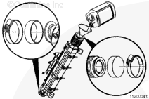
Cap the outlet end of the EGR cooler with parts supplied in the EGR cooler leak check kit, Part Number 3164225.
Completely fill the EGR cooler with mineral spirits.
Cap the gas inlet end of the EGR cooler with parts supplied in the EGR cooler leak check kit, Part Number 3164225.
When using solvents, acids, or alkaline materials for cleaning, follow the manufacturer’s recommendations for use. Wear goggles and protective clothing to reduce the possibility of personal injury.
WARNING
Wear appropriate eye and face protection when using compressed air. Flying debris and dirt can cause personal injury.
Drain the mineral spirits from the EGR cooler and properly dispose of the liquid.
Use compressed air to dry the inside of the EGR cooler and remove any loose debris or particles.
Cap the outlet end of the EGR cooler with parts supplied in service kit, Part Number 3164225.
Completely fill the EGR cooler with water.
Cap the gas inlet end of the EGR cooler with parts supplied in service kit, Part Number 3164225.
Drain the water from the EGR cooler and properly dispose of the liquid.
Use compressed air to dry the inside of the EGR cooler.
Clean the EGR cooler connection with safety solvent and dry with compressed air.
Inspect the EGR valve where the EGR cooler connection attaches to the EGR valve. Replace the EGR valve if cracks or other damage is found. Refer to Procedure 011-022 in Section 11.
Replace the EGR cooler if cracks or other damage is found on the EGR cooler.
When using solvents, acids, or alkaline materials for cleaning, follow the manufacturer’s recommendations for use. Wear goggles and protective clothing to reduce the possibility of personal injury.
WARNING
Wear appropriate eye and face protection when using compressed air. Flying debris and dirt can cause personal injury.
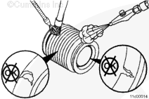
With the EGR connection tube attached, clean the cooler end of the EGR connection tube with safety solvent.
Dry with compressed air.
Inspect the EGR connection tube for cracks or other damage, while still attached to the block. Replace the EGR connection tube if necessary. Refer to Procedure 011-025 in Section 11.
When using solvents, acids, or alkaline materials for cleaning, follow the manufacturer’s recommendations for use. Wear goggles and protective clothing to reduce the possibility of personal injury.
WARNING
Wear appropriate eye and face protection when using compressed air. Flying debris and dirt can cause personal injury.
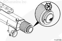
Clean the EGR cooler connection with safety solvent and dry with compressed air.
Inspect the EGR cooler connection for cracks or other damage. Replace the EGR cooler connection if cracks or other damage is found. Refer to Procedure 011-024 in Section 11.
When using solvents, acids, or alkaline materials for cleaning, follow the manufacturer’s recommendations for use. Wear goggles and protective clothing to reduce the possibility of personal injury.
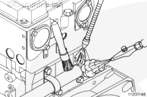
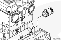
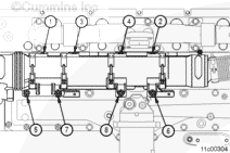
Clean the mounting surfaces with safety solvent to remove any coolant deposits or debris.
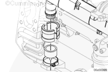
Clean the opening in the block where the EGR cooler coolant supply and vent jumper tubes are installed to remove any coolant deposits or debris. Otherwise, the o-ring joint can leak.
Clean the coolant supply and vent jumper tubes to remove any coolant deposits or debris.
Wear appropriate eye and face protection when using compressed air. Flying debris and dirt can cause personal injury.
WARNING
When using solvents, acids, or alkaline materials for cleaning, follow the manufacturer’s recommendations for use. Wear goggles and protective clothing to reduce the possibility of personal injury.
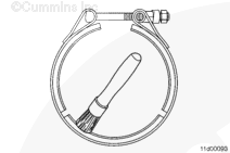
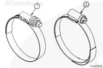
Inspect the v-band clamp threads for damage. Replace the clamp if damage is found.
Inspect the EGR cooler and the EGR cooler clamping plates for cracks or other damage. Replace the EGR cooler or EGR cooler clamping plates if cracks or other damage is found.
Do not use chlorinated water to clean or rinse the EGR cooler. Chlorides are very corrosive to the stainless alloys internal and external to the EGR cooler.
Cap the outlet end of the EGR cooler with the plastic caps supplied in the service kit, Part Number 4918655.
Completely fill the EGR cooler with safety solvent.
Cap the gas inlet end of the EGR cooler with the plastic cap supplied in the service kit.
Wear appropriate eye and face protection when using compressed air. Flying debris and dirt can cause personal injury.
WARNING
When using solvents, acids, or alkaline materials for cleaning, follow the manufacturer’s recommendations for use. Wear goggles and protective clothing to reduce the possibility of personal injury.
Drain the safety solvent from the EGR cooler and properly dispose of the liquid.
Use compressed air to dry the inside of the EGR cooler and remove any loose debris or particles.
Cap the outlet end of the EGR cooler with the plastic cap supplied in the service kit, Part Number 4918655.
Completely fill the EGR cooler with water.
Cap the gas inlet end of the EGR cooler with the plastic cap supplied in the service kit.
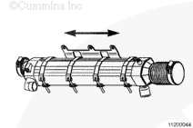
Shake the cooler by hand, from end to end, for approximately 30 seconds.
Drain the water from the EGR cooler and properly dispose of the liquid.
Use compressed air to dry the inside of the EGR cooler.
Inspect the exhaust manifold where the EGR cooler connection attaches to the exhaust manifold. Replace the exhaust manifold if cracks or other damage is found. Refer to Procedure 011-007 in Section 11.
Replace the EGR cooler if cracks or other damage is found.
Wear appropriate eye and face protection when using compressed air. Flying debris and dirt can cause personal injury.
WARNING
When using solvents, acids, or alkaline materials for cleaning, follow the manufacturer’s recommendations for use. Wear goggles and protective clothing to reduce the possibility of personal injury.
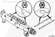
Clean the EGR cooler bellows with safety solvent and dry with compressed air.
Inspect the EGR cooler bellows for cracks or other damage.
Replace the EGR cooler bellows if cracks or other damage is found.
When using solvents, acids, or alkaline materials for cleaning, follow the manufacturer’s recommendations for use. Wear goggles and protective clothing to reduce the possibility of personal injury.
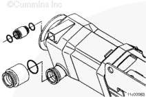
Clean the mounting surfaces with safety solvent to remove any coolant deposits or debris.
Clean the opening in the block where the EGR cooler coolant return elbow connection is installed, to remove any coolant deposits or debris. Otherwise, the press-in-place seal joint can leak.
Clean the EGR cooler coolant supply and return jumper tubes to remove any coolant deposits or debris.
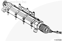
Cap off the coolant inlet and vents of the cooler with the parts supplied in the EGR cooler leak check kit, Part Number 3164225. Jumper tube, Part Number 3683068, and jumper tube, Part Number 3682540, from the cooler, are also used.
Make sure the air pressure regulator is closed and connect compressed air to the pressure regulator.
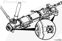
Completely submerge the EGR cooler in room temperature water. Make sure to submerge the cooler vertically with the outlet end down so that air can not be left in the open (gas) side of the cooler.
Apply 206 kPa [30 psi] of air pressure to the cooler.
Inspect for bubbles escaping from uncapped gas ports of the EGR cooler or from the exterior shell of the cooler.
Verify that bubbles are not a result of loose fittings or trapped air.
Bubbles coming from a damaged EGR cooler can be very small and/or not in a steady stream.
If bubbles are not observed, the EGR cooler is reusable.
If the EGR cooler is not reusable, inspect the turbocharger turbine housing for any signs of coolant deposits.
If coolant deposits are found, run the variable geometry operational test with INSITE™ electronic service tool to make sure the turbocharger is operating properly.
Coolant deposits can be identified as dried white deposits coating the inside of the turbine housing.
Remove the parts supplied in the EGR cooler leak check kit, Part Number 3164225.
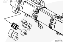
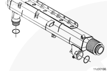
Install the plug with the o-ring supplied in Service Kit, Part Number 4918655, into the coolant inlet side of the EGR cooler, use a M8 x 1.25 capscrew.
Wear appropriate eye and face protection when using compressed air. Flying debris and dirt can cause personal injury.
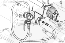
Make sure the air pressure regulator and ball-type valve are closed and connect compressed air supply to the pressure regulator.
Apply 620 kPa [90 psi] of air pressure to the EGR cooler.
Inspect for air escaping the EGR cooler assembly as a result of loose fittings by spraying the exterior of the EGR cooler and all lines and fittings with a mixture of mild soap and water.
Wear appropriate eye and face protection when using compressed air. Flying debris and dirt can cause personal injury.
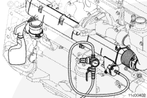
Shut off the air supply to the regulator by using the ball-valve and disconnect the compressed air supply.
Record the time at which the air supply was shutoff and the air pressure shown on the air pressure regulator gauge.
Measure and record the air pressure after 15 minutes.
If the measured pressure loss in the EGR cooler is more than 35 kPa [5 psi] in 15 minutes, the EGR cooler is not reusable.
NOTE: If the EGR cooler is not reusable, inspect the air pressure regulator, air lines, ball-valve, o-rings and other components carefully for leaks. A mixture of mild soap and water may be sprayed onto the assembly to aid in leak detection.
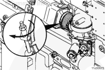
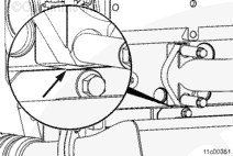
Keep all protective caps on the EGR cooler in place while grinding clearance in the upper mounting bracket. Failure to do so could cause progressive damage to the engine once the EGR cooler is installed. It’s important to prevent any debris from entering the cooler.
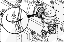
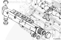
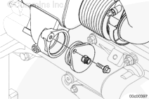
Inspect for an interference fit between the upper EGR cooler mounting bracket and the lower portion of the exhaust manifold flange. If this interference is present, grind a clearance on the upper EGR cooler mounting bracket in the area shown in the illustration.
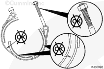
Do not use air tools to remove or install the nut on the v-band clamp. Use of these tools can seriously damage the threads or the bolt and cause the clamp to not be able to be reused.
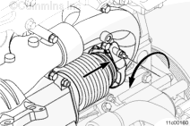
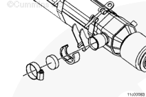
Position the v-band clamp onto the EGR cooler inlet connection.
NOTE: If the EGR cooler is being replaced due to a malfunction that caused an internal coolant leak, the crankcase breather element must be replaced.
NOTE: If the EGR cooler is being replaced due to a malfunction that caused an internal coolant leak, the EGR differential pressure sensor tubes should be inspected for deposits. If deposits are found, replace the EGR differential pressure tubes.
NOTE: If a malfunction resulted in oil, excessive fuel, or excessive black smoke entering the exhaust system, the aftertreatment system must be inspected. Refer to the Aftertreatment Diesel Oxidation Catalyst and Aftertreatment Diesel Particulate Filter Reuse Guidelines, Bulletin 4021600.
Hello, I'm Jack, a diesel engine fan and a blogger. I write about how to fix and improve diesel engines, from cars to trucks to generators. I also review the newest models and innovations in the diesel market. If you are interested in learning more about diesel engines, check out my blog and leave your feedback.
View all posts by Jack
 WARNING


 CAUTION


;)
;)
;)
;)
;)
;)
;)
;)
;)
;)
;)
;)
;)
;)
;)
;)
;)
;)
;)
;)
;)
;)
;)
;)
;)
;)
;)
;)
;)
;)
;)
;)
;)
;)
;)
;)
;)
;)
;)
;)
;)
;)
;)
;)
;)
;)
;)
;)
;)
;)
;)
;)
;)
;)
;)
;)
;)
;)
;)
;)
;)
;)
;)
;)
;)
;)
;)
;)
;)
;)
;)
;)
;)
;)
;)
;)
;)
;)