Do not remove the pressure cap from a hot engine. Wait until the coolant temperature is below 50°C [120°F] before removing the pressure cap. Heated coolant spray or steam can cause personal injury.
WARNING
Coolant is toxic. Keep away from children and pets. If not reused, dispose of in accordance with local environmental regulations.
Drain the cooling system. Refer to Procedure 008-018.
Remove the air intake piping. Refer to the OEM service manual.
Remove the charge air cooler piping. Refer to Procedure 010-027.
Remove the upper radiator hose. Refer to the OEM service manual.
Remove the vent line. Refer to the OEM service manual.
Remove the engine coolant temperature sensor. Refer to Procedure 019-019 in the ISX CM871 and ISM CM876 Electronic Control System Troubleshooting and Repair Manual, Bulletin 4021560.
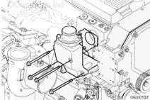
Remove the turbocharger coolant return line. Refer to Procedure 010-041.
Remove the OEM coolant sensor(s). Refer to the OEM service manual.
Remove the exhaust gas pressure sensor. Refer to 019-376 in the ISX CM871 and ISM CM876 Electronic Control System Troubleshooting and Repair Manual, Bulletin 4021560
Remove the turbocharger actuator air line, if required. Refer to Procedure 010-113.
Remove the heat shield, if required. Refer to Procedure 011-032.
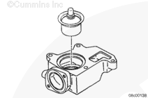
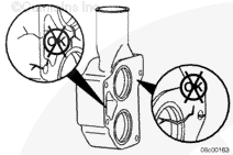
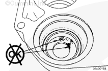
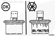
Inspect the bottom of the thermostat bores in thermostat cover for corrosion, pitting, or erosion that would cause leakage past the thermostats when they are in the open position.
Replace the thermostat seals, if damaged. Refer to Procedure 008-016.
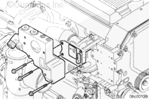
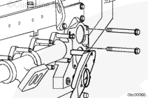
To reduce the possibility of a coolant leak, the 90-degree elbow on the thermostat housing must be positioned appropriately and tightened before the thermostat housing is installed on the cylinder head.
Use two thermostat housing capscrews to align the thermostat housing.
Install the thermostat housing, gasket, and three capscrews to the cylinder block.
Tighten the three thermostat housing mounting capscrews.
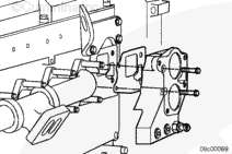
Install the refrigerant compressor mounting bracket. Refer to Procedure 009-055.
Install the refrigerant compressor. Refer to Procedure 009-051.
Install the EGR cooler coolant return tube, if required. Refer to Procedure 011-031.
Install the EGR cooler connection tube, if required. Refer to Procedure 011-024.
Install the EGR valve, if required. Refer to Procedure 011-022.
Install the heat shield, If required. Refer to Procedure 011-032.
Install the turbocharger actuator air line. Refer to Procedure 010-113.
Install the exhaust gas pressure sensor. Refer to Procedure 019-376 in the ISX CM871 and ISM CM876 Electronic Control System Troubleshooting and Repair Manual, Bulletin 4021560.
Install the turbocharger coolant return line. Refer to Procedure 010-041.
Install the vent line. Refer to the OEM service manual.
Install the OEM coolant sensor(s). Refer to the OEM service manual.
Install the engine coolant temperature sensor. Refer to Procedure 019-019 in the ISX CM871 and ISM CM876 Electronic Control System Troubleshooting and Repair Manual, Bulletin 4021560.
Install the upper radiator hose. Refer to the OEM service manual.
Install the charge air cooler piping. Refer to Procedure 010-027.
Install the air intake piping. Refer to the OEM service manual.
Fill the cooling system. Refer to Procedure 008-018.
Operate the engine until the coolant temperature reaches 70°C [158°F] and check for leaks.
Hello, I'm Jack, a diesel engine fan and a blogger. I write about how to fix and improve diesel engines, from cars to trucks to generators. I also review the newest models and innovations in the diesel market. If you are interested in learning more about diesel engines, check out my blog and leave your feedback.
View all posts by Jack
 WARNING


;)
;)
;)
;)
;)
;)
;)
;)
;)
;)
;)
;)
;)
;)
;)
;)
;)
;)
;)
;)
;)
;)
;)
;)
;)
;)
;)
;)