|
Knock Sensor Circuit – Shorted Low, Front Sensor
|

Overview
| CODE | REASON | EFFECT |
| Fault Code: 572 PID: S91 SPN: 1353 FMI: 4 LAMP: Amber SRT: |
Knock Sensor Circuit – Shorted Low, Front Sensor. Knock sensor circuit shorted low. |
Knock control will be disabled. |
|
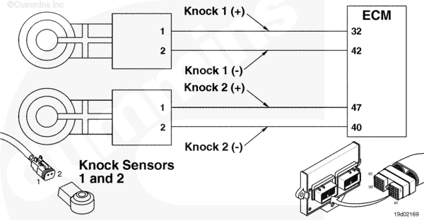
Knock Sensor 1 and 2 Circuit |
 |
Circuit Description
The electronic control module (ECM) uses this sensor to determine if the engine is knocking so it can protect the engine.
Component Location
The knock sensor 1 is located on the side of the engine, on the block, above the air compressor on the C and L Gas Plus engines. The B series engine has Knock Sensor 1 located on the cylinder head intake cover capscrew.
Knock Sensor 2 is located on the top of the engine, on the cylinder head, beside cylinder number 6 on the C and L Gas Plus engines. On B series engine, Knock Sensor 2 is located on the left side of the block near the ECM.
Cautions and Warnings
 CAUTION CAUTION To reduce the possibility of damaging a new ECM, all other active fault codes must be investigated prior to replacing the ECM. |
|
CAUTION To reduce the possibility of pin and harness damage, use the following test lead when taking a measurement: |
Troubleshooting Steps
| STEPS | SPECIFICATIONS | |
|---|---|---|
| STEP 1. | Check the fault codes. | |
| STEP 1A. Read the fault codes. | Fault Code 572 active? | |
| STEP 2. | Check the knock sensor. | |
| STEP 2A. Inspect the engine harness and knock sensor connector pins. | Dirty or damaged pins? | |
| STEP 2B. Read the fault codes. | Fault Code 572 active? | |
| STEP 3. | Check the engine harness. | |
| STEP 3A. Inspect the engine harness and ECM connector pins. | Dirty or damaged pins? | |
| STEP 3B. Read the fault codes. | Fault Code 572 active? | |
| STEP 3C. Check for an open circuit. | Less than 10 ohms? | |
| STEP 3D. Check for a short circuit to ground. | Greater than 100k ohms? | |
| STEP 3E. Check for a short circuit from pin to pin. | Greater than 100k ohms? | |
| STEP 3F. Check for an inactive fault code. | Fault Code 572 inactive? | |
| STEP 4. | Clear the fault codes. | |
| STEP 4A. Disable the fault code. | Fault Code 572 inactive? | |
| STEP 4B. Clear the inactive fault codes. | All fault codes cleared? | |
Guided Step 1 – Check the fault codes.
| Guided Step 1A – Read the fault codes. | |
|---|---|
Conditions
Action
|
|
|
Fault Code 572 active? |
|
| YES | NO |
| No Repair | No Repair |
Guided Step 2 – Check the knock sensor.
| Guided Step 2A – Inspect the engine harness and knock sensor connector pins. | |
|---|---|
Conditions
Action
Refer to the circuit diagram or wiring diagram for component pin identification. For general inspection techniques, refer to Component Connector and Pin Inspection, Procedure 019-361. |
|
|
Dirty or damaged pins? |
|
| YES | NO |
|
Repair the damaged pins. Repair or replace the engine harness, or replace the sensor, whichever has the damaged pins.
|
No Repair |
| Guided Step 2B – Read the fault codes. | |
|---|---|
Conditions
Action
|
|
|
Fault Code 572 active? |
|
| YES | NO |
| No Repair | No Repair |
Guided Step 3 – Check the engine harness.
| Guided Step 3A – Inspect the engine harness and ECM connector pins. | |
|---|---|
Conditions
Action
Refer to the circuit diagram or wiring diagram for component pin identification. For general inspection techniques, refer to Component Connector and Pin Inspection, Procedure 019-361. |
|
|
Dirty or damaged pins? |
|
| YES | NO |
|
Repair the damaged pins. Repair or replace the engine harness, or replace the ECM, whichever has the damaged pins.
|
No Repair |
| Guided Step 3B – Read the fault codes. | |
|---|---|
Conditions
Action
|
|
|
Fault Code 572 active? |
|
| YES | NO |
| No Repair | No Repair |
| Guided Step 3C – Check for an open circuit. | ||
|---|---|---|
Conditions
Action
Refer to the circuit diagram or wiring diagram for component pin identification. For general resistance measurement techniques, refer to the Resistance Measurements Using a Multimeter and Wiring Diagram, Procedure 019-360. |
|
|
|
Less than 10 ohms? |
||
| YES | NO | |
| No Repair |
Repair or replace the engine harness. |
|
| Guided Step 3D – Check for a short circuit to ground. | ||
|---|---|---|
Conditions
Action
Refer to the circuit diagram or wiring diagram for component pin identification. For general resistance measurement techniques, refer to the Resistance Measurements Using a Multimeter and Wiring Diagram, Procedure 019-360. |
|
|
|
Greater than 100k ohms? |
||
| YES | NO | |
| No Repair |
Repair or replace the engine harness. |
|
| Guided Step 3E – Check for a short circuit from pin to pin. | ||
|---|---|---|
Conditions
Action
Refer to the circuit diagram or wiring diagram for component pin identification. For general resistance measurement techniques, refer to the Resistance Measurements Using a Multimeter and Wiring Diagram, Procedure 019-360. |
|
|
|
More than 100k ohms? |
||
| YES | NO | |
| No Repair |
Repair or replace the engine harness. |
|
;)
;)
;)
;)
;)
;)
;)
;)
| Guided Step 3F – Check for an inactive fault code. | |
|---|---|
Conditions
Action
|
|
|
Fault Code 572 inactive? |
|
| YES | NO |
| No Repair |
Replace the ECM. Call for pre-authorization. Refer to Procedure 019-031. |
Guided Step 4 – Clear the fault codes.
| Guided Step 4A – Disable the fault code. | |
|---|---|
Conditions
Action
|
|
|
Fault Code 572 inactive? |
|
| YES | NO |
| No Repair | No Repair |
| Guided Step 4B – Clear the inactive fault codes. | |
|---|---|
Conditions
Action
|
|
|
All fault codes cleared? |
|
| YES | NO |
| No Repair | No Repair |
|
Repair complete
|
Appropriate troubleshooting charts
|