This component or assembly weighs greater than 23 kg [50 lb]. To prevent serious personal injury, be sure to have assistance or use appropriate lifting equipment to lift this component or assembly.
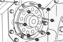
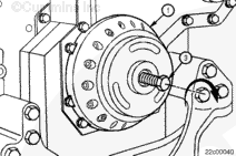
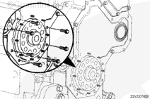
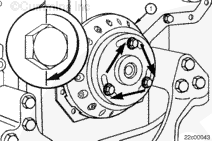
Position the replacer plate (1) over the crankshaft end and against the crankshaft seal. The large notch between the teeth needs to bridge the raised gear cover surface.
Make certain that the alignment of the three welded nuts on the crankshaft seal are positioned into the counterbore slots of the replacer plate (1).
Install a capscrew (4) with a flat washer (5) in the upper slot of the replacer plate to hold it in position
Tighten the capscrews by hand until a slight resistance is felt. Do not overtighten the capscrews or the seal nuts can break off causing damage to the seal and leading to front cover damage.
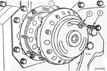
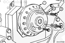
Use a small allen wrench to thread the removal tool capscrews (2) through the replacer plate and into the seal nuts.
Tighten the socket head capscrews (2) clockwise into the three seal removal nuts that are welded on the crankshaft seal until a slight resistance is felt.
Remove the capscrew in the upper slot of the replacer plate (1).
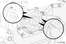
NOTE: All lower gear covers have either a beveled half groove, or a full o-ring groove under the crankshaft seal flange.
Full o-ring groove covers contain an o-ring in the lower gear cover groove and were only used prior to June 5, 1999. The lower gear cover must be replaced if installing a new seal. Refer to Procedure 001-080 (Gear Cover, Lower).
The position of the front crankshaft seal on the crankshaft is determined by the position of the lower gear cover.
The lower gear cover is mounted to the gear cover housing using clearance holes. This allows for slight movement of the cover when the mounting capscrews are loose.
The unitized crankshaft seal must be centered on the crankshaft for correct operation.
The seal attaches to the lower gear cover, and must be installed with the lower gear cover capscrews loose and the cover free to move.
In order for the seal to be properly centered on the crankshaft during assembly and maintain its location during operation, the following installation instructions must be followed.
The crankshaft seal removal and installation tool correctly centers the seal and correctly positions the dust seal portion of the seal on the crankshaft.
Failure to loosen and remove the mounting capscrews from the gear cover can cause the front crankshaft seal to be misaligned and cause premature seal wear.
The front gear cover must be aligned as follows:
Removing the gear cover mounting capscrews around the crankshaft seal allows the replacer plate to set against the gear cover during seal installation.
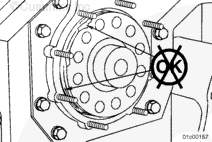
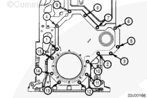
Remove the gear cover mounting capscrews around the crankshaft seal.
Loosen the remaining mounting capscrews on the gear cover so the cover can move freely.
Failure to follow the installation and tightening sequence can lead to the crankshaft seal being off center and installed at the wrong depth causing premature seal wear.
CAUTION
Never use a hammer or mallet to install the seal. Use of a hammer can damage the crankshaft seal and/or crankshaft.
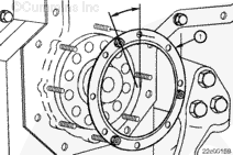
The seal removal and installation tool has provisions for any seal nut orientation, although one seal nut must always be located at the 11 o’clock position.
Do not use lubricants on the crankshaft seal.
Position the crankshaft seal (1) onto the crankshaft until the gear cover studs are protruding through the seal carrier mounting holes.
The crankshaft seal must be pressed evenly. If the crankshaft seal is not pressed in evenly the seal can be damaged.
Inspect the crankshaft seal during installation to make certain it is being pressed evenly.
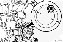
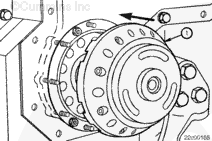
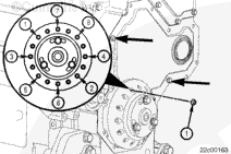
Tighten the capscrew(s) no more than ½ of a revolution at a time, alternating in a clockwise pattern until the replacer plate (1) bottoms out against the face of the lower gear cover.
To maintain the cover position while the replacer plate is removed, tighten the two gear cover mounting capscrews, as indicated by the arrows in the graphic.
Install the crankshaft seal mounting nuts (1) through the holes provided in the replacer plate.
This component or assembly weighs greater than 23 kg [50 lb]. To prevent serious personal injury, be sure to have assistance or use appropriate lifting equipment to lift this component or assembly.
Hello, I'm Jack, a diesel engine fan and a blogger. I write about how to fix and improve diesel engines, from cars to trucks to generators. I also review the newest models and innovations in the diesel market. If you are interested in learning more about diesel engines, check out my blog and leave your feedback.
View all posts by Jack
 WARNING


 CAUTION
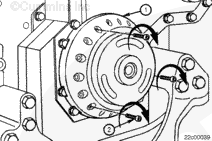


;)
;)
;)
;)
;)
;)
;)
;)
;)
;)
;)
;)
;)
;)
;)
;)
;)
;)
;)
;)
;)
;)
;)
;)
;)
;)
;)
;)
;)
;)
;)
;)