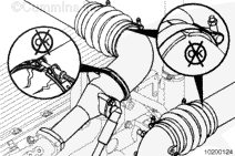
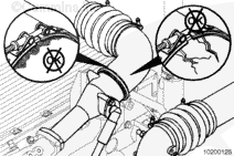
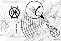
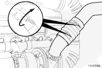
Engine intake air must be filtered to prevent dirt and debris from entering the engine. If intake air piping is damaged or loose, unfiltered air will enter the engine and cause premature wear.
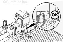
Inspect the intake air piping for cracked hoses, and damaged or loose clamps.
Replace damaged pipes and tighten loose clamps, as necessary, to make sure the air intake system does not leak.
Torque Value: 8 n.m [71 in-lb]
Check for corrosion of the intake system piping under the clamps and hoses. Corrosion can allow corrosive products and dirt to enter the air intake system.
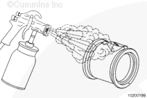
Disassemble and clean the intake air piping as required.
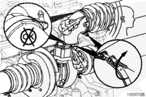
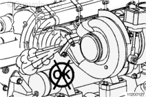
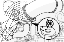
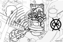
Do not over-torque turbine housing v-band. If v-band is overtorqued it will provide less clamp load to the turbine housing and bearing housing flanges which can result in damage to turbocharger.
The noise can be caused by a turbine housing sealing surface exhaust leak.
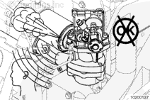
Engine intake air must be filtered to prevent dirt and debris from entering the engine. If intake air piping is damaged or loose, unfiltered air will enter the engine and cause premature wear.
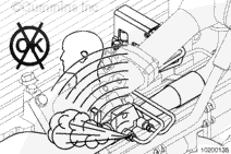
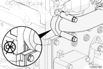
Inspect for loose clamps or damage between the intake air piping, air cleaner, turbocharger, charge air cooler, and intake manifold.
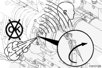
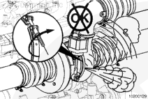
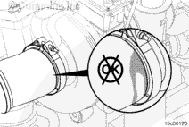
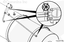
Removing the turbine housing v-band tamper proofing on any variable geometry turbocharger will void the Cummins warranty coverage.
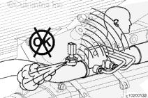
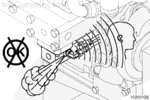
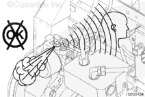
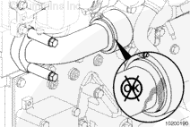
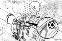
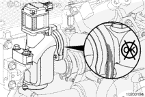
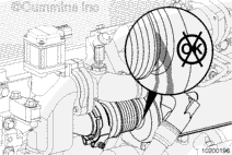
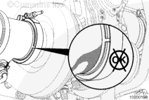
Variable Geometry Turbocharger – Turbine housing sealing surface air leak.
For variable geometry turbochargers, the turbine v-band nut has a tamper proof clamp. Therefore the torque spec for the turbine v-band can not be checked.
The purpose of the tamper proofing is to prevent disturbing this joint. Any loosening of the v-band or adjusting of the orientation of the turbine housing will affect the sliding nozzle clearances and will damage the turbocharger and result in poor performance.
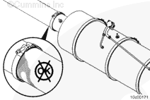
Indications of leakage are soot streaks from the joint and/or an audible whistle from the engine. The turbocharger must be replaced if there are any indications of leakage from the turbine housing v-band joint.
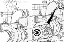
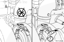
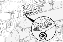
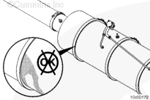
Aftertreatment Inlet Connection – Inspect for visible soot streaks at the torca clamp or v-band clamp joint. Also inspect for loose or damaged insulation wrapping (if applicable).
Inlet to Catalyst Connection – Inspect for visible soot streaks at the v-band joint.
If soot streaks are found, check for fault codes relating to high differential pressure in the aftertreatment system. If no fault codes are found, tighten the v-band clamp. Refer to Procedure 011-050 in Section 11.
Operate the engine at full throttle and check for an exhaust leak.
If a leak is still present, remove and replace with a new gasket and v-band clamp.
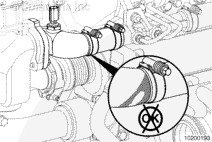
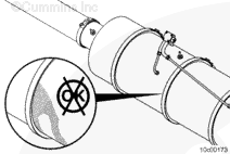
Aftertreatment Diesel Oxidation Catalyst to Aftertreatment Diesel Particulate Filter Connection – Inspect for visible soot streaks at the v-band joint.
If soot streaks are found, check for fault codes relating to high differential pressure in the aftertreatment system. If no fault codes are found, tighten the v-band clamp. Refer to Procedure 011-049 in Section 11.
Operate the engine at full throttle and check for an exhaust leak.
If a leak is still present, remove and replace with a new gasket and v-band clamp.
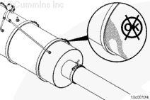
Aftertreatment Diesel Particulate Filter to Outlet Connection – Inspect for visible soot streaks at the v-band joint.
If soot streaks are found, check for fault codes relating to high differential pressure in the aftertreatment system. If no fault codes are found, tighten the v-band clamp. Refer to Procedure 011-041 in Section 11.
Operate the engine at full throttle and check for an exhaust leak.
If a leak is still present, remove and replace with a new gasket and v-band clamp.
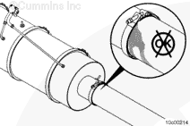
Aftertreatment Outlet Connection – Inspect for visible soot streaks at the v-band joint.
If soot streaks are found, check for fault codes relating to high differential pressure in the aftertreatment system. If no fault codes are found, tighten the v-band clamp. Refer to Procedure 011-041 in Section 11.
Operate the engine at full throttle and check for an exhaust leak.
If a leak is still present, remove and replace with a new gasket and v-band clamp.
Aftertreatment Diesel Particulate Filter Differential Pressure Sensor Tube Connections – Inspect for visible soot streaks at the threaded bosses or hose connections.
If soot streaks are found at the threaded boss, loosen the differential pressure sensor tube nut, apply a coating of anti-seize compound, and tighten the differential pressure sensor tube nut. Refer to Procedure 011-047 in Section 11.
Operate the engine at full throttle and check for an exhaust leak.
If a leak is still present at the threaded boss, remove and replace the differential pressure sensor tube.
If a leak is still present at the hose connection, replace the differential pressure sensor tube or differential pressure sensor, depending on which component the hose is permanently attached to.
Hello, I'm Jack, a diesel engine fan and a blogger. I write about how to fix and improve diesel engines, from cars to trucks to generators. I also review the newest models and innovations in the diesel market. If you are interested in learning more about diesel engines, check out my blog and leave your feedback.
View all posts by Jack
 CAUTION


 WARNING
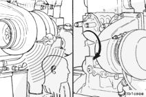
;)
;)
;)
;)
;)
;)
;)
;)
;)
;)
;)
;)
;)
;)
;)
;)
;)
;)
;)
;)
;)
;)
;)
;)
;)
;)
;)
;)
;)
;)
;)
;)
;)
;)
;)
;)
;)
;)
;)
;)
;)
;)
;)
;)
;)
;)
;)
;)
;)
;)
;)
;)
;)
;)
;)
;)
;)
;)
;)
;)
;)
;)
;)
;)
;)
;)
;)
;)
;)
;)
;)
;)
;)
;)