Engine Performance Troubleshooting Tree – CM554 Electronic Control System with CAPS Fuel System

Symptoms
- Engine Acceleration or Response Poor
- Cranking Fuel Pressure is Low
- Engine Operating Fuel Pressure is Low
- Engine Decelerates Slowly
- Engine Difficult to Start or Will Not Start (Exhaust Smoke)
- Engine Difficult to Start or Will Not Start (No Exhaust Smoke)
- Engine Power Output Low
- Engine Runs Rough at Idle
- Engine Runs Rough or Misfires
- Engine Speed Surges at Low or High Idle
- Engine Speed Surges Under Load or in Operating Range
- Smoke, Black – Excessive
- Smoke, White – Excessive
- Engine Shuts Off or Dies Unexpectedly or Dies During Deceleration
- Engine Starts But Will Not Keep Running
- Engine Will Not Reach Rated Speed (RPM)
- Intake Manifold Pressure (Boost) is Below Normal
How To Use This Tree
This symptom tree can be used to troubleshoot all of the performance-based symptoms listed above. Start by performing Step 1 troubleshooting. Step 2 will ask a series of questions and will provide a list of troubleshooting steps to perform, depending on the symptom. Perform the list of troubleshooting in the sequence shown in the Specifications/Repair section of the tree.
Shop Talk
Driveability is a term that in general describes vehicle performance on the road. Driveability problems for an engine can be caused by several different factors. Some of the factors are engine-related and some are
not. Before troubleshooting, it is important to determine the exact complaint and whether the engine has a real driveability problem or if it simply does
not meet driver expectations.
Low power is a term that is used in the field to describe many different performance problems. Low power is defined as the inability of the engine to produce the power necessary to move the vehicle at a speed that can be reasonably expected under the given conditions of load, grade, wind, and so on.
Poor acceleration or response is described as the inability of the vehicle to accelerate satisfactorily from a stop or from the bottom of a grade. It can also be the lag in acceleration during an attempt to pass or overtake another vehicle at conditions less than rated speed and load. Poor acceleration or response is difficult to troubleshoot because it can be caused by several factors.
Troubleshooting Steps
| STEPS | SPECIFICATIONS | |
|---|---|---|
| STEP 1. | Perform basic troubleshooting procedures. | |
| STEP 1A. Check for active fault codes or high counts of inactive fault codes. | Active fault codes or high counts of inactive fault codes? | |
| STEP 1B. Perform basic troubleshooting checks. | All steps have been verified to be correct? | |
| STEP 2. | Determination of engine symptom. | |
| STEP 2A. Low power, poor acceleration, or poor response. | Is the engine symptom low power, poor acceleration, or poor response? | |
| STEP 2B. Engine misfire, engine speed surge, or engine speed unstable. | Is the engine symptom engine misfire, engine speed surge, or engine speed unstable? | |
| STEP 2C. Excessive white or black smoke. | Is the engine symptom excessive white or black smoke? | |
| STEP 2D. Low intake manifold pressure. | Is the engine symptom low boost pressure? | |
| STEP 2E. Engine will not start or difficult to start, or engine shuts off unexpectedly. | Is the symptom engine will not start or difficult to start, or engine shuts off unexpectedly? | |
| STEP 3. | No-start troubleshooting procedures. | |
| STEP 3A. Check the ECM keyswitch voltage. | Is the keyswitch voltage equal to battery voltage? | |
| STEP 3B. Check the ECM battery supply voltage. | Is the ECM battery supply voltage equal to the battery voltage? | |
| STEP 3C. Verify the operation of cold weather starting aids. | If equipped, are cold weather starting aids operating correctly? | |
| STEP 3D. Check the fuel lift pump pressure. | Is the fuel lift pump pressure greater than the specifications outlined in Procedure 005-045 (Fuel Lift Pump) in the ISC, ISCe, QSC8.3, ISL and QSL9 Engines Troubleshooting and Repair Manual, Bulletin 4021418? | |
| STEP 3E. Verify fuel pressure sensor accuracy. | Is the accumulator pressure value less than 34.5 bar [500 psi]? | |
| STEP 3F. Check the accumulator pressure. | Is accumulator pressure greater than 293 bar [4250 psi] while cranking? | |
| STEP 3G. Use INSITE™ electronic service tool to check the CPS crank state. | Does CPS state read Valid Sync while cranking? | |
| STEP 3G-1. Check and adjust speed/position sensor air gap. | ||
| STEP 3H. Measure gear pump pressure. | Is the fuel gear pump pressure greater than the specifications outlined in Procedure 005-089 (Fuel Pump Gear Pump Module) in the ISC, ISCe, QSC8.3, ISL and QSL9 Engines Troubleshooting and Repair Manual, Bulletin 4021418? | |
| STEP 3I. Perform the injection control valve (IVC) click test. | Does the injection control valve pass the click test? | |
| STEP 3J. Perform the pumping control valve (PCV) click test. | Do the pumping control valves pass the click test? | |
| STEP 3K. Check the distributor rotor timing. | Distributor rotor timing is correct as outlined in Procedure 005-072 (Rotor, CAPS Fuel Injection Pump) in the ISC, ISCe, QSC8.3, ISL and QSL9 Engines Troubleshooting and Repair Manual, Bulletin 4021418? | |
| STEP 3L. Inspect the gear pump coupling for wear. | Is the gear pump drive shaft or coupling worn? | |
| STEP 4. | Fuel system troubleshooting procedures. | |
| STEP 4A. Check for fault codes. | Are fuel system fault codes active? | |
| STEP 4B. Check the CAPS fuel pump wiring. | All fuel pump wiring is undamaged and is properly connected? | |
| STEP 4C. Check transorb diode. | Does the rough running, black smoke, or surge complaint continue? | |
| STEP 4D. Check for air in the high-pressure pump fuel supply. | Is air present in the fuel supply? | |
| STEP 4E. Measure the fuel inlet restriction. | Is the fuel inlet restriction less than the specifications outlined in Procedure 006-020 (Fuel Inlet Restriction) in the ISC, ISCe, QSC8.3, ISL and QSL9 Engines Troubleshooting and Repair Manual, Bulletin 4021418? | |
| STEP 4F. Measure the fuel gear pump pressure. | Is the fuel gear pump pressure greater than the specifications outlined in Procedure 005-089 (Fuel Pump Gear Pump Module) in the ISC, ISCe, QSC8.3, ISL and QSL9 Engines Troubleshooting and Repair Manual, Bulletin 4021418? | |
| STEP 4G. Perform the injection control valve click test. | Does the injection control valve pass the click test? | |
| STEP 4H. Perform the pumping control valve click test. | Do the pumping control valves pass the click test? | |
| STEP 4I. Measure fuel drain line restriction. | Is the drain line restriction less than specification? | |
| STEP 4J. Perform the single cylinder cutout test. | Can the miss or excessive smoke be attributed to a single cylinder? | |
| STEP 4K. Verify the fuel temperature sensor is within specification. | Is the fuel temperature sensor within specification? | |
| STEP 4L. Check for excessive injector drain leakage. | Are only a few drops of fuel per minute draining from the back of the cylinder head? | |
| STEP 4M. Pop test the injectors. | The injector spray pattern is correct and the injectors pop between 275 and 300 bar [3989 and 4351 psi]? | |
| STEP 4N. Inspect the gear pump coupling for wear. | Is the gear pump drive shaft or coupling worn? | |
| STEP 5. | Air handling troubleshooting procedures. | |
| STEP 5A. Inspect the turbocharger blades for damage. | Damage found on turbocharger blades? | |
| STEP 5B. Check the turbocharger axial and radial clearances. | Are the turbocharger axial and radial bearing clearances within specification? | |
| STEP 5C. Inspect the wastegate actuator rod for travel. | Does the wastegate actuator rod move? | |
| STEP 5C-1. Inspect the wastegate actuator rod for travel. | ||
| STEP 6. | Electronic feature troubleshooting procedures. | |
| STEP 6A. Verify throttle pedal travel. | Does the throttle position read zero when the throttle is released and 100 percent when the throttle is depressed? | |
| STEP 6B. Check ambient air pressure sensor accuracy (if equipped). | Is the reading within 50.8 mm-Hg [2 in-Hg] of local barometric pressure? | |
| STEP 6C. Check intake manifold pressure sensor accuracy. | Is the intake manifold pressure reading less than 102 mm-Hg [4 in-Hg]? | |
| STEP 6D. Verify electronic feature settings are correct. | Are the electronic features set correctly? | |
| STEP 7. | Base engine troubleshooting procedures. | |
| STEP 7A. Verify overhead adjustments are correct. | Are the overhead settings within the reset limits? | |
| STEP 7B. Verify engine brake adjustment (if equipped). | Are the engine brake settings within the reset limits? | |
| STEP 7C. Inspect the charge air cooler. | Is the charge air cooler free of cracks, holes, or other damage? | |
| STEP 7D. Check air intake restriction. | Is air intake restriction greater than 635 mm-H 2O [25 in-H 2O]? |
|
| STEP 7E. Check exhaust restriction. | Is exhaust back pressure less than 72 mm-Hg [3 in-Hg]? | |
| STEP 7F. Check engine blowby. | Are the engine blowby measurements within specification? | |
| STEP 7F-1. Verify turbocharger contribution to engine blowby. | ||
Guided Step 1 – Perform basic troubleshooting procedures.
| Guided Step 1A – Check for active fault codes or high counts of inactive fault codes. | |
|---|---|
Conditions
ActionCheck for active fault codes.
|
|
|
Active fault codes or high counts of inactive fault codes? |
|
| YES | NO |
| No Repair | No Repair |
|
Go to appropriate fault code troubleshooting tree
|
|
| Guided Step 1B – Perform basic troubleshooting checks. | |
|---|---|
ActionThe following items must be checked or verified before continuing:
|
|
|
All steps have been verified to be correct? |
|
| YES | NO |
| No Repair |
Correct the condition and verify complaint is no longer present after repair. |
|
Repair complete
|
|
Guided Step 2 – Determination of engine symptom.
| Guided Step 2A – Low power, poor acceleration, or poor response. | |
|---|---|
ActionInterview the driver and verify the complaint. |
|
|
Is the engine symptom low power, poor acceleration, or poor response? |
|
| YES | NO |
|
Perform the troubleshooting steps in the recommended order listed below:
|
No Repair |
|
Perform the troubleshooting steps suggested in the repair procedure
|
|
| Guided Step 2B – Engine misfire, engine speed surge, or engine speed unstable. | |
|---|---|
ActionInterview the driver and verify the complaint. |
|
|
Is the engine symptom engine misfire, engine speed surge, or engine speed unstable? |
|
| YES | NO |
|
Perform the troubleshooting steps in the recommended order listed below:
|
No Repair |
|
Perform the troubleshooting steps suggested in the repair procedure.
|
|
| Guided Step 2C – Excessive white or black smoke. | |
|---|---|
ActionInterview the driver and verify the complaint. |
|
|
Is the engine symptom excessive white or black smoke? |
|
| YES | NO |
|
Perform the troubleshooting steps in the recommended order listed below:
|
No Repair |
|
Perform the troubleshooting steps suggested in the repair procedure
|
|
| Guided Step 2D – Low intake manifold pressure. | |
|---|---|
ActionInterview the driver and verify the complaint. |
|
|
Is the engine symptom low boost pressure? |
|
| YES | NO |
|
Perform the troubleshooting steps in the recommended order listed below:
|
No Repair |
|
Perform the troubleshooting steps suggested in the repair procedure
|
|
| Guided Step 2E – Engine will not start or difficult to start, or engine shuts off unexpectedly. | |
|---|---|
ActionInterview the driver and verify the complaint. |
|
|
Is the symptom engine will not start or difficult to start, or engine shuts off unexpectedly? |
|
| YES | NO |
|
Perform the troubleshooting steps in the recommended order listed below:
|
No Repair |
|
Perform the troubleshooting steps suggested in the repair procedure
|
Return to correct symptom tree
|
Guided Step 3 – No-start troubleshooting procedures.
| Guided Step 3A – Check the ECM keyswitch voltage. | |
|---|---|
Conditions
ActionMeasure the signal voltage from the keyswitch input SIGNAL wire of the OEM harness to the engine block ground. Measure the keyswitch voltage with the keyswitch in the ON position and also with the keyswitch in the START position. Refer to the wiring diagram for connector pin identification. |
|
|
Is the keyswitch voltage equal to battery voltage? |
|
| YES | NO |
| No Repair |
Repair or replace the OEM power harness or keyswitch, or check the battery connections. |
|
Repair complete
|
|
| Guided Step 3B – Check the ECM battery supply voltage. | |
|---|---|
Conditions
ActionMeasure the voltage from the ECM battery supply (+) to the ECM battery supply (-) pins in the OEM harness connector. Refer to the wiring diagram for connector pin identification. |
|
|
Is the ECM battery supply voltage equal to the battery voltage? |
|
| YES | NO |
| No Repair |
Repair or replace the ECM power harness. Check the battery connections and fuse terminals. |
|
Repair complete
|
|
| Guided Step 3C – Verify the operation of cold weather starting aids. | |
|---|---|
ActionMake sure the intake air heater and other cold starting aids are operational, if equipped. |
|
|
If equipped, are cold weather starting aids operating correctly? |
|
| YES | NO |
| No Repair |
Repair cold weather starting aids. |
|
Repair complete
|
|
| Guided Step 3D – Check the fuel lift pump pressure. | |
|---|---|
ActionMeasure the fuel lift pump output pressure. At initial key-on, the lift pump will run for 30 seconds, then it will stop. Lift pump pressure can be low if fuel prime was lost. Multiple keyswitch cycles can be necessary to prime the fuel system using the electric lift pump. |
|
| YES | NO |
| No Repair |
Find and repair the cause of low lift pump pressure. |
|
Repair complete
|
|
| Guided Step 3E – Verify fuel pressure sensor accuracy. | |
|---|---|
Conditions
ActionUse INSITE™ electronic service tool to monitor accumulator pressure. The engine speed |
|
|
Is the accumulator pressure value less than 34.5 bar [500 psi]? |
|
| YES | NO |
| No Repair |
Replace the fuel pressure sensor. Refer to Service Bulletin, CAPS Fuel Pressure Sensor Kit, |
|
Repair complete
|
|
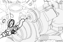
| Guided Step 3F – Check the accumulator pressure. | |
|---|---|
Conditions
ActionUse INSITE™ electronic service tool to read accumulator pressure while cranking the engine. |
|
|
Is accumulator pressure greater than 293 bar [4250 psi] while cranking? |
|
| YES | NO |
| No Repair | No Repair |
| Guided Step 3G – Use INSITE™ electronic service tool to check the CPS crank state. | |
|---|---|
Conditions
ActionUse INSITE™ electronic service tool to monitor CPS state while cranking the engine. |
|
|
Does CPS state read Valid Sync while cranking? |
|
| YES | NO |
| No Repair |
Troubleshoot the engine speed sensor circuit. See Fault Codes 115 and 121. |
| Guided Step 3G-1 – Check and adjust the speed/position sensor air gap. | |
|---|---|
Conditions
ActionCheck and adjust the speed/position sensor air gap.
|
|
|
Are the sensor(s) depth measurements within specification? |
|
| YES | NO |
|
No Repair. |
Replace the engine speed/position sensor(s). |
|
Repair Complete
|
|
| Guided Step 3H – Measure gear pump pressure. | |
|---|---|
Conditions
ActionMeasure the gear pump pressure while cranking the engine. |
|
| YES | NO |
| No Repair | No Repair |
| Guided Step 3I – Perform the injection control valve (ICV) click test. | |
|---|---|
Conditions
ActionUse INSITE™ electronic service tool to perform the ICV click test. |
|
|
Does the injection control valve pass the click test? |
|
| YES | NO |
| No Repair |
Replace the injection control valve stator. |
|
Repair complete
|
|
| Guided Step 3J – Perform the pumping control valve (PCV) click test. | |
|---|---|
Conditions
ActionUse INSITE™ electronic service tool to perform the front and rear PCV test. |
|
|
Do the pumping control valves pass the click test? |
|
| YES | NO |
|
Replace the injection control valve module. |
Replace the accumulator module. |
|
Repair complete
|
Repair complete
|
| Guided Step 3K – Check the distributor rotor timing. | |
|---|---|
Conditions
ActionInspect the distributor rotor timing and check for a seized rotor. |
|
| YES | NO |
| No Repair |
Replace the fuel injection pump. |
|
Repair complete
|
|
| Guided Step 3L – Inspect the gear pump coupling for wear. | |
|---|---|
Conditions
ActionInspect the gear pump drive shaft coupling and shaft for wear. |
|
|
Is the gear pump drive shaft or coupling worn? |
|
| YES | NO |
|
Replace the gear pump module. |
Replace the injection control valve. |
|
Repair complete
|
Repair complete
|
Guided Step 4 – Fuel system troubleshooting procedures.
| Guided Step 4A – Check for fault codes. | |
|---|---|
Conditions
ActionUse INSITE™ electronic service tool to read the fault code information. Check for active fuel system fault codes related to the complaint. |
|
|
Are fuel system fault codes active? |
|
| YES | NO |
|
Follow the appropriate troubleshooting tree. |
No Repair |
|
Repair complete
|
|
| Guided Step 4B – Check the CAPS fuel pump wiring. | |
|---|---|
ActionCheck the injection control valve, pressure control valve, fuel pressure sensor, and fuel temperature sensor wiring for damage, cuts, and loose connections. |
|
|
All fuel pump wiring is undamaged and is properly connected? |
|
| YES | NO |
| No Repair |
Replace the malfunctioning fuel system component. |
|
Repair complete
|
|
| Guided Step 4C – Check the transorb diode. | |
|---|---|
Conditions
ActionUnplug the fuel pressure sensor. |
|
|
Does the rough running, black smoke, or surge complaint continue? |
|
| YES | NO |
| No Repair |
Replace the transorb diode. |
|
Repair complete
|
|
| Guided Step 4D – Check for air in the high-pressure pump fuel supply. | |
|---|---|
|
Is air present in the fuel supply? |
|
| YES | NO |
|
Locate and correct the cause of air ingestion in the fuel supply system. Sources of air ingestion include loose fuel filters, loose fuel line fittings, loose or cracked fuel tank stand-pipes, and severe restrictions in the fuel supply lines and filters. |
No Repair |
|
Repair complete
|
|
| Guided Step 4E – Measure the fuel inlet restriction. | |
|---|---|
Conditions
ActionMeasure the fuel inlet restriction. |
|
| YES | NO |
| No Repair |
Locate the cause of the high inlet restriction. Check the OEM fuel inlet plumbing, fuel filters, and lift pump check valve. |
|
Repair complete
|
|
| Guided Step 4F – Measure the fuel gear pump pressure. | |
|---|---|
Conditions
ActionMeasure the gear pump pressure while the engine is at the rated condition. |
|
| YES | NO |
| No Repair |
Replace the fuel gear pump module. |
|
Repair complete
|
|
| Guided Step 4G – Perform the injection control valve (ICV) click test. | |
|---|---|
Conditions
ActionUse INSITE™ electronic service tool to perform the ICV click test. |
|
|
Does the injection control valve pass the click test? |
|
| YES | NO |
| No Repair |
Replace the injection control valve stator. |
|
Repair complete
|
|
| Guided Step 4H – Perform the pumping control valve (PCV) click test. | |
|---|---|
Conditions
ActionUse INSITE™ electronic service tool to perform the front and rear PCV click test. |
|
|
Do the pumping control valves pass the click test? |
|
| YES | NO |
| No Repair |
Replace the accumulator module. |
|
Repair complete
|
|
| Guided Step 4I – Measure fuel drain line restriction. | |
|---|---|
Conditions
ActionCheck the fuel drain line restriction. |
|
|
Is the drain line restriction less than specification? |
|
| YES | NO |
| No Repair |
Look for causes of high drain line restriction, such as kinked or blocked fuel lines. |
|
Repair complete
|
|
| Guided Step 4J – Perform the single cylinder cutout test. | |
|---|---|
Conditions
ActionOperate the engine at loaded conditions.
|
|
|
Can the miss or excessive smoke be attributed to a single cylinder? |
|
| YES | NO |
|
Replace the fuel injector in the cylinder that was identified using the single cylinder cutout test. |
No Repair |
|
Repair complete
|
|
| Guided Step 4K – Verify the fuel temperature sensor is within specification. | |
|---|---|
Conditions
ActionCheck the resistance of the fuel temperature sensor.
|
|
|
Is the fuel temperature sensor within specification? |
|
| YES | NO |
| No Repair |
Replace the fuel temperature sensor. |
|
Repair complete.
|
|
| Guided Step 4L – Check for excessive injector drain leakage. | |
|---|---|
Conditions
ActionRun the engine at low idle while monitoring the amount of fuel draining from the back of the cylinder head. |
|
|
Are |
|
| YES | NO |
| No Repair |
A damaged connection between the high-pressure connector and an injector has been detected. Remove all high-pressure connectors and check for burrs or deformation around the tip of the injector. |
|
Repair complete
|
|
| Guided Step 4M – Pop test the injectors. | |
|---|---|
ConditionsActionPop test the injectors and check for proper spray pattern. |
|
|
The injector spray pattern is correct and the injectors pop between 275 and 300 bar [3989 and 4351 psi]? |
|
| YES | NO |
| No Repair |
Replace the malfunctioning injector. |
|
Repair complete
|
|
| Guided Step 4N – Inspect the gear pump coupling for wear. | |
|---|---|
Conditions
ActionInspect the gear pump drive shaft coupling and shaft for wear. |
|
|
Is the gear pump drive shaft or coupling worn? |
|
| YES | NO |
|
Replace the gear pump module. |
Replace the injection control valve. |
|
Repair complete
|
Repair complete
|
Guided Step 5 – Air handling troubleshooting procedures.
| Guided Step 5A – Inspect the turbocharger blades for damage. | |
|---|---|
Conditions
ActionInspect the compressor and turbine blades for damage or wear. |
|
|
Damage found on turbocharger blades? |
|
| YES | NO |
|
Replace the turbocharger assembly. |
No Repair |
|
Repair complete
|
|
| Guided Step 5B – Check the turbocharger axial and radial clearance. | |
|---|---|
Conditions
ActionCheck the turbocharger for correct axial and radial clearance. |
|
|
Are the turbocharger axial and radial bearing clearances within specification? |
|
| YES | NO |
| No Repair |
Replace the turbocharger. |
|
Repair complete
|
|
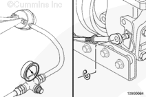
| Guided Step 5C – Inspect the wastegate actuator rod for travel. | ||
|---|---|---|
Conditions
ActionApply a regulated air supply of 138 kPa [20 psi] to the actuator and check for actuator movement. |
|
|
|
Does the wastegate actuator rod move? |
||
| YES | NO | |
| No Repair | No Repair | |
|
Repair complete
|
||
| Guided Step 5C-1 – Inspect the wastegate actuator rod for travel. | ||
|---|---|---|
Conditions
ActionApply a regulated air supply of 138 kPa [20 psi] to the actuator and check for actuator movement. |
|
|
|
Does the wastegate actuator rod move? |
||
| YES | NO | |
|
Move the wastegate lever on the turbocharger back and forth to check for smooth operation. Replace the turbocharger assembly if the wastegate is seized. |
Replace the wastegate actuator. |
|
|
Repair complete
|
Repair complete
|
|
Guided Step 6 – Electronic feature troubleshooting procedures.
| Guided Step 6A – Verify throttle pedal travel. | |
|---|---|
Conditions
ActionUse INSITE™ electronic service tool to monitor the throttle position while fully depressing and releasing the throttle pedal. |
|
|
Does the throttle position read zero when the throttle is released and 100 percent when the throttle is depressed? |
|
| YES | NO |
| No Repair |
Determine and correct the cause of the throttle pedal restriction. |
|
Repair complete
|
|
| Guided Step 6B – Check ambient air pressure sensor accuracy (if equipped). | |
|---|---|
Conditions
ActionStart INSITE™ Data Monitor/Logger and compare INSITE™ reading for Barometric Air Pressure to the local barometric pressure using the table below. Refer to Procedure 018-028 (Barometric Pressure at Altitude) in Section V. |
|
|
Is the reading within 50.8 mm-Hg [2 in-Hg] of local barometric pressure? |
|
| YES | NO |
| No Repair |
Replace the barometric pressure sensor. |
|
Repair Complete
|
|
| Guided Step 6C – Check intake manifold pressure sensor accuracy. | |
|---|---|
Conditions
ActionStart INSITE™ electronic service tool Data/Monitor/Logger and read the value of intake manifold pressure. |
|
|
Is the intake manifold pressure reading less than 102 mm-Hg [4 in-Hg]? |
|
| YES | NO |
| No Repair |
Replace the intake manifold pressure sensor. |
|
Repair complete
|
|
| Guided Step 6D – Verify electronic feature settings are correct. | |
|---|---|
Conditions
ActionUse INSITE™ electronic service tool to verify the following adjustable parameters are set correctly:
|
|
|
Are the electronic features set correctly? |
|
| YES | NO |
| No Repair |
Use INSITE™ electronic service tool to correct programmable features. |
|
Repair complete
|
|
Guided Step 7 – Base engine troubleshooting procedures.
| Guided Step 7A – Verify overhead adjustments are correct. | |
|---|---|
Conditions
ActionMeasure the overhead settings. |
|
|
Are the overhead settings within the reset limits? |
|
| YES | NO |
| No Repair |
Adjust the overhead settings. |
|
Repair complete
|
|
| Guided Step 7B – Verify engine brake adjustment (if equipped). | |
|---|---|
Conditions
ActionVerify the engine brakes are operating correctly. |
|
|
Are the engine brake settings within the reset limits? |
|
| YES | NO |
| No Repair |
Adjust the engine brake settings. |
|
Repair complete
|
|
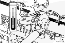
| Guided Step 7C – Inspect the charge air cooler. | ||
|---|---|---|
ActionInspect the charge air cooler for cracks, holes, or other damage. |
|
|
|
Is the charge air cooler free of cracks, holes, or other damage? |
||
| YES | NO | |
| No Repair |
Repair the charge air cooler assembly. |
|
|
Repair complete
|
||

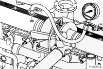
| Guided Step 7D – Check air intake restriction. | ||
|---|---|---|
ActionCheck the intake system restriction by installing a vacuum gauge into the air intake system. |
|
|
|
Is air intake restriction greater than 635 mm-H |
||
| YES | NO | |
|
Correct the cause of high intake air restriction. Check for a plugged air filter or restricted air intake piping. |
No Repair | |
|
Repair complete
|
||
| Guided Step 7E – Check exhaust restriction. | ||
|---|---|---|
ActionCheck the exhaust system back pressure by installing a pressure gauge into the exhaust system just past the turbocharger outlet. |
|
|
|
Is exhaust back pressure less than 72 mm-Hg [3 in-Hg]? |
||
| YES | NO | |
| No Repair |
Inspect the exhaust system for the source of high restriction. |
|
|
Repair complete
|
||
;)
;)
;)
;)
;)
;)
;)
;)
;)
;)
| Guided Step 7F – Check engine blowby. | |
|---|---|
|
Are the engine blowby measurements within specification? |
|
| YES | NO |
| No Repair | No Repair |
|
Return to Step 2 or contact a Cummins Inc. service representative for further diagnostic and troubleshooting instructions.
|
Go to Step 7F-1.
|
| Guided Step 7F-1 – Verify turbocharger contribution to engine blowby. | |
|---|---|
Conditions
ActionLoad engine to rated rpm on a chassis dynamometer. |
|
|
Has the total engine blowby dropped more than 30 percent of the total? |
|
| YES | NO |
|
Replace the turbocharger assembly. |
The engine may need to be rebuilt. See the engine rebuild specifications. |
|
Repair complete.
|
Repair complete.
|